

Dodge Avenger (2008) – fuse and relay box
Diagrams of fuse and relay boxes – Dodge Avenger
Applies to vehicles manufactured in the years:
2008.
The integrated power module (fuse box) is located in the engine compartment near the air filter assembly.
This hub includes blade fuses and mini fuses. A label identifying each item can be printed on the inside of the cover.
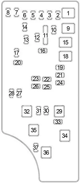
| Recess | Cartridge fuse | mini fuse | Description |
|---|---|---|---|
| 1 | 40 amp green | – | – |
| 2 | – | 20 A yellow | – |
| 3 | – | 10 A red | Battery Power – Top Mounted Center Stop Lamp (CHMSL) / Brake Switch |
| 4 | – | 10 A red | Battery powered – ignition switch |
| 5 | – | 20 A yellow | Trailer Towing – If Equipped |
| 6 | – | 10 A red | Ignition Off Consumption (IOD) – Power Mirror Switch / A / C Controls |
| 7 | – | 30 A green | Ignition OFF (IOD) Sense 1 |
| 8 | 30 A green | Ignition OFF (IOD) Sense 2 | |
| 9 | 40 amp green | Battery Power – Electric Seats – If Equipped / PZEV Air Pump – If Equipped | |
| 10 | – | 20 A yellow | Battery Powered – Cab Compartment Node (CCN) |
| 11 | – | 15 Amp lt blue | Possibility to choose a power outlet |
| 12 | – | 20 A yellow | – |
| 13 | – | 20 A yellow | – |
| 14 | 10 A red | Consumption After Ignition Off (IOD) – Cab Compartment Node (CCN) / Interior lighting | |
| 15 | 40 amp green | – | Battery Power – Radiator Fan Relay |
| 16 | – | 15 A mid. blue | IGN Run / ACC-Cigarette Lighter / PWR Sunroof Mod |
| 17 | – | 10 A red | Ignition Off Consumption (IOD) – Wireless Control Module (WCM) / Clock / Steering Control Module (SCM) |
| 18 | 40 amp green | Battery Operated – Automatic Shut Off Relay (ASD) | |
| 19 | – | 20 A yellow | Ignition Off Consumption (IOD) – Power amp 2 supplies – if equipped |
| 20 | – | 15 A mid. blue | Ignition Off Consumption (IOD) – Radio |
| 21 | – | 10 A red | – |
| 22 | – | 10 A red | Ignition Start – A / C Controls / Heated Cup Holder – If equipped |
| 23 | – | 15 A mid. blue | Automatic shutdown relay (ASD) feed 3 |
| 24 | – | 25 A Clean | Battery powered – PWR sunroof power supply |
| 25 | – | 10 A red | Ignition Operation – Heated Mirrors – If equipped |
| 26 | – | 15 A mid. blue | Automatic shutdown relay (ASD) feed 2 |
| 27 | – | 10 A red | Ignition sequence – passenger classification module (OCM) / passenger restraining controller (ORC) |
| 28 | – | 10 A red | Ignition sequence – passenger classification module (OCM) / passenger restraining controller (ORC) |
| 29 | – | – | Hot car (no fuse) |
| 30 | – | 20 A yellow | Ignition Operation – Heated Seats – If Equipped |
| 31 | – | 10 A red | – |
| 32 | 30 Amp Pink | Automatic shutdown relay (ASD) power supply 1 | |
| 33 | – | 10 A red | Battery Power – Switch Block / Diagnostic Connector / Powertrain Control Module (PCM) |
| 34 | 30 Amp Pink | Battery Power – Antilock Braking System (ABS) Module – If Equipped / Electronic Stability Program (ESP) Module – If Equipped | |
| 35 | 40 amp green | – | Battery Power – Anti-lock Braking Module (ABS) – If Equipped / Electronic Stability Program (ESP) Module – If Equipped |
| 36 | 30 Amp Pink | – | Battery Power – Passenger’s Door Module (PDM) / Driver’s Door Module (DDM) |
| 37 | – | 25 And transparent | – |