Dodge Dakota (1997-2000) – fuse and relay box
Fuse and relay boxes diagram – Dodge Dakota
Applies to vehicles new in years:
1997, 1998, 1999, 2000.
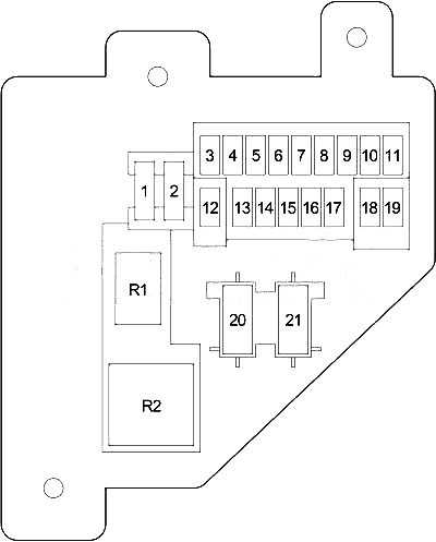
Distribution board fuse box diagram
The fuses are located on the left side of the dashboard.

| Number | Amperes [A] | Description |
|---|---|---|
| 1 | 20 | Headlamp Flasher Relay, A / C Compressor Clutch Relay, Horn Relay, Central Timing Module (VTSS) |
| 2 | 15 | Park / Neutral Position Switch (Automatic Transaxle), Reverse Lamp Switch (Manual Transaxle) |
| 3 | 10 | ABS |
| 4 | 15 | Instrument cluster |
| 5 | 5 | Air conditioning heating control, heating control (except air conditioning), ash receiver lamp, radio, instrument cluster |
| 6 | 20 | Wiper relay, multi-function switch, central time module, wiper motor |
| 7 | 15 | Blower motor relay, A / C compressor clutch relay |
| 8 | 10 | Radio |
| 9 | 10 | Diesel: Engine control module, fuel heater relay |
| 10 | Gasoline: Powertrain control module, fuel pump relay, auto shut-off relay, radiator fan relay | |
| 10 | 15 | Combined blinker |
| 11 | 10 | EVAP / Purge solenoid, upper console, central time module |
| 12 | 15 | Glove box lamp, radio, data link connector, under hood lamp / switch, dome lamp, overhead console, power mirror switch |
| 13 | 20 | Central timer switch, window / door lock switch |
| 14 | 15 | Headlight switch (city lamp, tail / stop lamp, registration lamp, air conditioning heater control, heating control (except air conditioning), ash receiver lamp, radio, instrument cluster) |
| 15 | 15 | Lighter |
| 16 | – | – |
| 17 | 10 | Instrument cluster |
| 18 | 10 | Airbag control module |
| 19 | 10 | Airbag control module, passenger airbag on / off switch |
| 20 | 25 | Electric window / door lock switch |
| 21 | – | – |
| R1 | Horn | |
| R2 | Combined blinker | |
Diagram of the fuse box in the engine compartment
| № | AND | Protected circuit |
|---|---|---|
| A | 25 | Diesel: A / C compressor clutch relay, engine control module, powertrain control module, electric vacuum modulator |
| 15 | Gasoline: oxygen sensor | |
| B | 15 | Left headlight |
| C. | 20 | Fog lamp relay |
| D | 25 | Combined blinker |
| E. | 20 | Stop lamp switch |
| F. | 10 | Diesel: Auto shutdown relay, powertrain control module |
| 20 | Gasoline: Transmission control relay | |
| G. | 15 | Right headlight |
| 1 | 50 | Diesel: fuel heater relay |
| 20 | Gasoline: Powertrain control module, fuel pump relay | |
| 2 | 20 | Diesel: power socket |
| thirty | Gasoline: Radiator fan relay | |
| 3 | 50 | Diesel: Auto shut-off relay (fuel injection pump, glow plug relay, fuse: “A”) |
| thirty | Gasoline: Auto shut-off relay (Fuel Injector, Ignition Coil, Powertrain Control Module, Fuse: “A”) | |
| 4 | 50 | Diesel: Glow plug relay |
| 20 | Gasoline: Power socket | |
| 5 | 40 | Blower motor relay |
| 6 | 50 | Diesel: Glow plug relay |
| 7 | 50 | Fuse (passenger compartment): “1”, “4”, “12”, “13”, “14”, “21” |
| 8 | thirty | ABS |
| 9 | 40 | Starter relay, ignition switch (fuses (passenger compartment): “2”, “3”, “7”, “18”, “20”), radiator fan relay, fuel pump relay, auto shut-off relay |
| 10 | 40 | Ignition switch (starter relay, fuse (passenger compartment): “6”, “8”, “9”, “10”, “11”, “15”, “16”, “17”, “19”) |
| 11 | 140 | Generator |
| R1 | Mat | |
| R2 | Blower motor | |
| R3 | Starter | |
| R4 | – | |
| R5 | Fog light | |
| R6 | – | |
| R7 | Gasoline: gearbox check | |
| R8 | Air conditioning compressor clutch | |
| R9 | Automatic shutdown | |
| R10 | – | |
| R11 | Gasoline: Radiator fan | |
| R12 | Headlamp blinker | |
| R13 | Gasoline: fuel pump | |
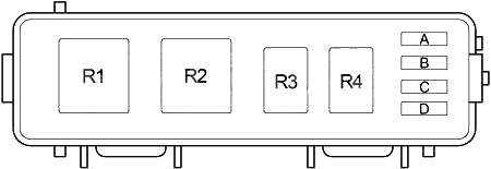
Engine compartment relay box
| Number | Amperes [A] | Description |
|---|---|---|
| 1 | – | – |
| 2 | – | – |
| 3 | – | – |
| 4 | – | – |
| R1 | – | |
| R2 | Fuel heater relay | |
| R3 | – | |
| R4 | – | |


