Dodge RAM 2500 (2011-2013) – fuse and relay box
Diagram of fuse and relay boxes – Dodge RAM 2500
Applies to vehicles new in years:
2011, 2012, 2013.
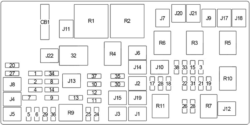
Diagram of the fuse box in the engine compartment
The Fully Integrated Power Module (TIPM) is located in the engine compartment near the battery. This hub includes blade fuses and mini fuses. A description of each fuse and component may be stamped on the inner cover, otherwise the bay number of each fuse is stamped on the inner cover as shown in the table below.

| Number | Amperes [A] | Description |
|---|---|---|
| 1 | 15 | Stop lamp switch |
| 2 | 20 | – |
| 3 | thirty | except 6.7L: Powertrain control module |
| 4 | – | – |
| 5 | 25 | 115V AC inverter |
| 6 | 20 | Cigar lighter (instrument panel) or power socket (front console), rain sensor |
| 7 | 20 | Rear power outlet or power outlet (center seat) |
| 8 | 20 | Front heated seat, steering wheel |
| 9 | 20 | Heated rear seats |
| 10 | 15 | Compass module, hands-free module, video screen module, satellite video module, universal garage door opener, toilet lamp |
| 11 | 10 | Air conditioning heating control, engine hood lamp |
| 12 | thirty | Radio, radio amplifier |
| 13 | 20 | Cluster, multi-function switch, steering column module, siren, tire pressure monitoring system, wireless control module |
| 14 | 20 | Reversing camera |
| 15 | 20 | Cluster, Multi-Function Switch, Steering Angle Sensor, Trailer Tow Module, Transfer Case Selector Switch, Interior Rearview Mirror, Fuel Heated Relay (6.7L), Oxygen Sensor Module, Powertrain Control Module (Except 3.7L), Module electric seat, audio telematics, daytime running light relay |
| 16 | 10 | Passenger restraint controller module (airbag) |
| 17 | – | – |
| 18 | 15 | Center stop lamp |
| 19 | 25 | Automatic shutdown (No.1, No.2) |
| 20 | 15 | Cluster, lower bank switch, upper bank switch, control module controller |
| 21 | 20 | Automatic switch-off (No. 3) |
| 22 | 10 | Horn (right) |
| 23 | 10 | Horn (left) |
| 24 | – | – |
| 25 | 20 | Gasoline: Fuel pump motor |
| 20 | Diesel: lifting pump | |
| 26 | 10 | Driver window / door lock switch |
| 27 | 10 | Ignition switch |
| 28 | 15 | except 6.7L: Powertrain control module (PCM) |
| 29 | 10 | Tire pressure monitoring system |
| 30 | 15 | Diagnostic connector |
| 31 | 20 | Backup lamp switch |
| 32 | 10 | Passenger restraint controller module (airbag) |
| 33 | 10 | Powertrain control module (PCM) |
| 34 | 10 | A / C Heater Control, Infrared Sensor, Parking Assist Module, Radiator Fan Relay (High) (Except 6.7L), Compass Module |
| 35 | 15 | Left front and rear parking lamps |
| 36 | 20 | Power socket (front console) or cigarette lighter (instrument panel) |
| 37 | 10 | Stop lamp switch, ABS, dynamics sensor |
| 38 | 25 | Door lock relay, driver door unlock relay, passenger door unlock relay |
| J1 | 40 | Tow trailer |
| J2 | thirty | Brake protection module |
| J3 | thirty | Diesel: Powertrain control module (PCM) |
| J4 | 25 | Driver’s door module |
| J5 | 25 | Passenger door module |
| J6 | 40 | ABS |
| J7 | thirty | ABS |
| J8 | 40 | Circuit breaker (CB1 – power socket) |
| J9 | thirty | – |
| J10 | thirty | Stabilizer module |
| J11 | thirty | Transfer case module |
| J12 | thirty | Rear window defogger |
| J13 | 60 | Fuse: “10”, “11”, “12”, “13” |
| J14 | 20 | Trailer tow lamps / Parking lamps |
| J15 | 40 | Front blower |
| J16 | – | – |
| J17 | 40 | Starter |
| J18 | 20 | Transmission range of the powertrain control module |
| J19 | 60 | Radiator Fan Relay (Low), Radiator Fan Relay (High) |
| J20 | thirty | Wiper on / off relay |
| J21 | 20 | Washer control |
| J22 | 25 | Sunroof module |
| CB1 | 25 | Electric seat |
| R1 | Ignition (Run / Acc) | |
| R2 | Ignition (run) | |
| R3 | Starter | |
| R4 | Run-Start | |
| R5 | Transmission Control Module (TCM) | |
| R6 | Parking lamp | |
| R7 | EBL | |
| R8 | – | |
| R9 | Blower motor | |
| R10 | Automatic shutdown | |
| R11 | Radiator fan (low) | |

