

Komatsu PC25-1 – fuse box
Komatsu PC25-1 – fuse box diagram
Year of production:
Fuse box
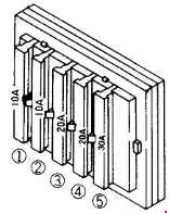
| Number | Amperes [A] | Description |
| 1 | 10 | Spare fuse |
| 2 | 10 | Engine control system;
Work tool lever lockout valve. |
| 3 | 20 | Monitor panel;
Mat*; Heater*; Interior lamp *; Radio* |
| 4 | 20 | Head lamp;
Drive selector valve. |
| 5 | 30 | Engine control system |
| * These items only apply to the machine with the cab. | ||
Fusible link
If the power does not turn on after turning the start switch to the ON position, the wire fusible link® may be cut, so remove the cover on the right side of the housing and check or replace.
