Mazda Tribute (2000-2011) – fuse and relay box
Diagrams of fuse boxes and relays – Mazda Tribute
Applies to vehicles manufactured in the years:
2000, 2001, 2002, 2003, 2004, 2005, 2006, 2007, 2008, 2009, 2010, 2011.
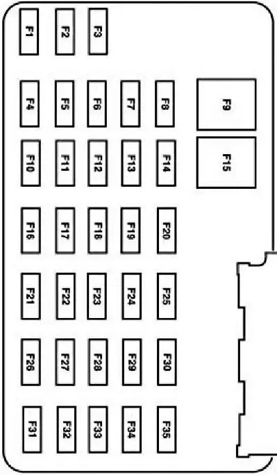
Fuse box in passenger compartment
It is located under the dashboard (lower part of the dashboard) on the passenger side and is covered with a protective cover. To gain access, it is enough to pry with a flat screwdriver for the special notch in the lid.
Type 1

Description
| 1 | 5A Electropneumatic valve of the fuel vapor container |
| 2 | 5A Fan relay, heated rear window |
| 3 | 10A Rear door wiper and washer motor |
| 4 | 10A 4WD control unit, instrument cluster |
| 5 | ABS and SRS 5A control unit |
| 6 | 10A Hazard warning lights, reversing lights |
| 7 | 10A Transponder signal amplifier, SRS control unit |
| 8 | 10A Instrument cluster, selector lock relay |
| 9 | 3A Engine and automatic transmission controller relay, fan relay, air conditioning relay |
| 10 | 20A Windshield wiper motor, windshield washer motor, intermittent wiper relay |
| 11 | 10A Starter relay, ignition key lock solenoid valve |
| 12 | 5A Radio and clock |
| 13 | Reserve |
| 14 | Cigarette lighter 20A |
| 15 | 15A Dimensions, headlights, trailer wiring relay |
| 16 | 10A Instrument panel, electric mirrors, electric control unit |
| 17 | 15A Luke |
| 18 | 5A Illumination of instrument cluster and instrument panel switches |
| 19 | 10A subwoofer |
| 20 | 15A Direction indicators, indicators, hazard lights |
| 21 | 10A Trailer side lights |
| 22 | 15A reserve |
| 23 | 15 / 20A buzzer |
| 24 | 15A Brake lights, ABS control unit, Engine and automatic transmission control unit, automatic transmission shift solenoid valves |
| 25 | 30A electric windows |
| 26 | 30A Central locking, ECM, electric seats |
| 27 | 10A Radio, instrument cluster, interior lighting |
| ACC | Relay for installing additional equipment |
Type 2
Description
| 1 | 15A Trailer lamps |
| 2 | Radio 5A (backlight) |
| 3 | 15A Front and rear parking lamps |
| 4 | 10A ignition switch |
| 5 | 2A Automatic Transmission Control Unit Relay, Fuel Pump Relay, Fan Relay, No.2 Fan High / Low Speed |
| 6 | 15A Auxiliary brake lights, brake lights, engine and automatic transmission control unit, ABS, cruise control |
| 7 | 10A instrument cluster, OBD, radio, electric side mirrors |
| 8 | 15A Fog lamps |
| 9 | 30A Central locking, electric seats |
| 10 | 15A Heated door mirrors |
| 11 | 15A Sunroof |
| 12 | Radio 15A |
| 13 | Reserve |
| 14 | Reserve |
| 15 | 30A electric window drive |
| 16 | 15A subwoofer |
| 17 | 15A dipped beam |
| 18 | AWD 18A system |
| 19 | 15A Anti-theft system |
| 20 | Buzzer 20A |
| 21 | 10A Rear door wiper and washer motor |
| 22 | 10A Interior rearview mirror, instrument cluster |
| 23 | 5A radio (power) |
| 24 | Cigarette lighter 20A |
| 25 | 20A Windshield Washer and Wiper Motor |
| 26 | 5A air conditioner |
| 27 | 5A Cruise control switch |
| 28 | 10A Instrument cluster |
| 29 | 10A Reversing lamps |
| 30 | Reserve |
| 31 | Reserve |
| 32 | 10A Selector lock relay |
| 33 | 15A SRS control unit, front passenger airbag deactivation indicator, front passenger seat sensor |
| 34 | 5A ABS unit, cruise control |
| 35 | 5A Heated seats, four-wheel drive |
Relays
On the back of the device there may be relays such as:
- Anti-pinch relay
- Starter relay
- Relay dimensions
- Horn relay
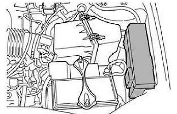
Fuse box in the engine compartment
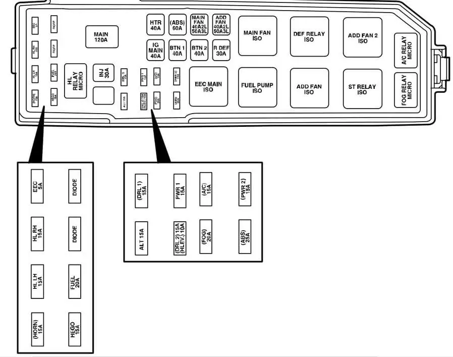
It is located on the left side, next to the battery, under the protective cover. On the reverse, the actual assignment of fuses and relays will be used.
Type 1
Description
| Horn | 15A Audible signal |
| H / LLH | 15A Left headlight |
| H / L RH | 15A Right headlight |
| EEC | 5A Engine management system |
| SOUTH | 15A Fuel injection system |
| FUEL | 20A fuel pump |
| DIODE | Diode |
| DIODE | Diode |
| H / L RELAY MICRO | Headlight relay |
| INJ | 30A Engine management system, MAF sensor, idle speed control valve |
| MAIN | Main fuse 120A |
| EVERYTHING | Generator 15A |
| (DRL) | 15A daylight system |
| (DRLZ) | 15A Daytime lighting control unit |
| (HLEV) | 10A headlight range control |
| PWR1 | 15A Socket for connecting additional devices |
| FOG | 20A fog lights |
| A / C | 15A A / C compressor clutch |
| (SECTION) | 25A anti-lock brake system |
| PWR2 | 15A Socket for connecting additional devices |
| MAIN IG | 40A Starter chain |
| HTR | 40A Fan motor, fan motor relay |
| BTN 1 | 40A Radio tape recorder, cigarette lighter, instrument cluster, electric mirrors |
| (SECTION) | ABS pump motor 60A |
| BTN 2 | 40A Radio tape recorder, instrument cluster, cruise control, electric seat adjustment, acoustic signal |
| MAIN FAN | Main fan 40 / 50A |
| RDEF | 30A Heated rear door windows |
| ADD FAN | 40 / 50A Additional fan |
| EEC MAIN ISO | Engine control relay |
| FUEL PUMP ISO | Fuel pump relay |
| MAIN FAN ISO | Low Fan Speed Relay (YF Motor) High Speed Fan Relay # 1 (AJ Motor) |
| ADD FAN ISO | High fan speed relay (YF motor) Low fan speed relay (AJ motor) |
| DEF RELAY ISO | Rear glass door heating relay |
| ST RELAY ISO | Starter relay |
| ADD FAN 2 ISO | Relay No.2 high fan speed (AJ motor) Medium fan speed relay (YF motor) |
| FOG RELAY MICRO | Fog lamp relay |
| A / C RELAY MICRO | A / C compressor clutch relay |
Type 2
Description
| 1 | 25A Instrument panel fuse |
| 2 | 25A headlights |
| 3 | 25A High beam headlamps, turn signals, interior lighting, headlamps |
| 4 | 5A Delayed power-off of some circuits after the ignition is turned off |
| 5 | 15A oxygen sensor heater |
| 6 | 20A gasoline pump |
| 7 | Relay RUN / ACC 40A – Cigar lighter, windshield wipers and tailgate wipers |
| 8 | 30A Engine and automatic transmission control unit, injectors and coils |
| 9 | Generator 15A |
| 10 | 30A Heated seats |
| 11 | 10A Engine and automatic gearbox control unit |
| 12 | 20A sockets for connecting additional equipment |
| 13 | 20A Fog lights (headlamps / lights) |
| 14 | 15A A / C compressor electromagnetic clutch, A / C relay |
| 15 | 30A anti-lock brake system |
| 16 * | 25A Instrument panel fuse |
| 17 | 50A Starter circuit |
| 18 | 40A fan motor |
| 19 | 40A Auxiliary relay – subwoofer, AWD system, low beam |
| 20 | Anti-lock braking system 60A |
| 21 | 40A Horn, auxiliary brake light, instrument cluster, central locking and electric seats |
| 22 | Radiator fan 40 / 50A |
| 23 | 40A Heated rear door window, parking lamp relay |
| 24 | 40 / 50A high / low speed fan |
| 25 | Siding |
| R2 | Relay for engine control unit and automatic transmission |
| R3 | Fuel pump relay |
| R4 | Radiator fan relay |
| R5 | Relay # 1 high / low fan speed |
| R7 | Starter relay |
| R8 | Relay # 2 high / low fan speed |
| R9 | Fog lamp relay (headlamps / lamps) |
| R10 | Air conditioner relay |
| D1 | Starter diode |
| D2 | Air conditioner diode |
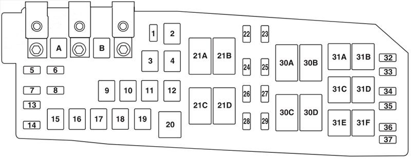
Type 3
Description
| A | 80A electronic power steering module (EPAS) |
| B | 125A Fuse panel in passenger compartment |
| 1 | 15A Heated mirror |
| 2 | 30A Rear heater |
| 3 | 20A Rear sockets (center console) |
| 4 | Reserve |
| 5 | 10A Powertrain Control Module (PCM) – Supports Power, PCM Relay, Canister Vent |
| 6 | Generator 15A |
| 7 | 15A Sunroof |
| 8 | 20A trailer parking lights |
| 9 | 50A Anti-lock brake system (ABS) |
| 10 | 30A Front wipers |
| 11 | Starter 30A |
| 12 | 40A fan motor |
| 13 | Air conditioner clutch 10A |
| 14 | 15A Trailer headlamps |
| 15 | Reserve |
| 16 | 40A Cooling fan 1 |
| 17 | 40A Cooling fan 2 |
| 18 | 20А ABS |
| 19 | 30A electric seats |
| 20 | Air conditioning drive relay |
| 21A | Rear defogger relay |
| 21B | Fuel relay |
| 21C | Fan relay |
| 21D | PCM relay |
| 22 | 20A fuel pump |
| 23 | Fuel injectors 15A |
| 24 | Not used |
| 25 | 5А ABS |
| 26 | 15A Ignition coils |
| 27 | Drive system component failure indicator light 10A |
| 28 | 20A Drive unit failure indicator light |
| 29 | 15А PCM |
| 30A | Cooling fan relay 1 |
| 30B | Starter relay |
| 30C | Main cooling fan relay |
| 30D | Cooling fan relay 2 |
| 31A | Tail light relay |
| 31B | Not used |
| 31C | Left turn trailer relay |
| 31D | Right trailer turn relay |
| 31E | Harbinger |
| 31F | Lockout relay |
| 32 | Not used |
| 33 | Air conditioner diode |
| 34 | Starter diode |
| 35 | Strat / Stop, Reversing Lamps, Rear Heater Relay |
| 36 | Reserve |

