
Renault Master II (1998-2003) – fuse and relay box
Diagrams of fuse and relay boxes – Renault Master
Applies to vehicles manufactured in the years:
1997, 1998, 1999, 2000, 2001, 2002, 2003.
Fuse box in passenger compartment
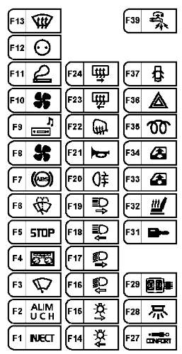
Renault Master – fuse box diagram – passenger compartment
| Number | Amperes [A] | Description |
| F1 | 5 | Injection computer + ignition feed;
Starter relay; Gearbox computer – behind ignition relay 1; Diagnostic socket. |
| F2 | 10 | UCH power supply;
Front row lighter; Door lock; Heated rear window; Idle speed regulator; Rear fog lamp relay; Gear shift indicator; Air conditioning control panel; Cruise control; Cruise control stop switch; Variable damping; Headlight adjustment; Heated windscreen; Parking proximity sensor computer; Cruise control; Gearbox load control; Computer of the controlled suspension. |
| F3 | 30 | Washer / Wiper Switch – UCH |
| F4 | 15 | Instrument panel;
Airbag pretensioner and computer; Tachograph |
| F5 | 15 | Brake switch;
Alternator; Reverse light switch; Reverse lamp relay. |
| F6 | 15 | Washer / wiper combination switch;
Windshield wiper motor. |
| F7 | 5 | ABS – Vehicle Speed Sensor |
| F8 | 15 | Air conditioning control relay;
Diesel fuel heater relay; Engine fuse board (position B track 4, for additional adaptations for reversing bornier (16-seater bus)). |
| F9 | 10 | Radio;
Multifunction display; Car phone communication interface; Central communication unit. |
| F10 | 30 | Air conditioning control panel |
| F11 | 10 | Lighter |
| F12 | 15 | Accessory socket |
| F13 | 5 | Injection computer;
Bornier reverse for additional adaptations (16-seater bus). |
| F14 | 5 | Left light;
Left tail light; Multifunction display; Central communication unit. |
| F15 | 5 | Right side light;
Right side light; License plate right side light; Connection to a caravan; Tachograph; Instrument panel. |
| F 16 | 10 | Left dipped beam;
Headlamp alignment control; Dashboard. |
| F17 | 10 | Right-hand dipped beam headlamp |
| F18 | 10 | Left high beam;
Instrument panel. |
| F19 | 10 | Right-hand high beam headlamp |
| F20 | 10 | Rear fog lamp relay;
Combination of a caravan. |
| F21 | 15 | Horn |
| F22 | 5 | Heated door mirrors |
| F23 | 20 | Heated rear right rear panel |
| F24 | 20 | Heated rear left rear panel |
| F25 | 10 | 16-seater bus:
Electric front door lock |
| F26 | 15 | 16-seater bus:
Electric rear right door lock |
| F27 | 5 | except for the 16-seater bus:
Controlled suspension computer |
| F28 | 15 | Tachograph;
Instrument panel; Alarm siren; Diagnostic socket; UCH alarm sensor. |
| F29 | 10 | Radio;
Multifunction display; Car phone communication interface; Central communication unit. |
| F30 | – | – |
| F31 | 5 | Impact sensor – UCH |
| F32 | 15 | Heated front seats;
Electric control of the side mirrors. |
| F33 | twenty | Driver control of the front passenger window;
Passenger window lift control. |
| F34 | twenty | Electric window control |
| F35 | twenty | Diesel fuel heater relay |
| F36 | 15 | with the exception of the 16-seater bus:
Emergency lights; 16-person bus: Emergency lights; Tachograph; Instrument panel; Alarm siren; Diagnostic socket; Alarm sensor. |
| F37 | thirty | Door control |
| F38 | thirty | 16-seater bus:
Consumer cut-off (powered by fuse F36) |
| F39 | thirty | Consumer switch (power supply to fuses F27, F28, F29 and F31) |
Passenger compartment fuse modules (except for 16-seater buses)
These modules are mounted on the passenger compartment relay board, on the left side of the dashboard.
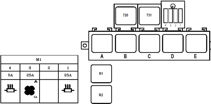 Renault Master – fuse box diagram – passenger compartment (except for the 16-passenger bus)
| Number | Amperes [A] | Description |
| F1 | 25 | 9-seater bus:
+ Battery powered before battery cutoff heating output |
| F2 | – | 9-seater bus:
unused |
| F3 | 25 | 9-seater bus:
Condenser relay |
| F4 | 5 | 9-seater bus:
+ Battery supply before battery cut-off, heating control |
| Relay | ||
| A | + After ignition 1 | |
| B | – | |
| C. | Passenger compartment fan assembly speed 4 | |
| D | Independent heating cut-off | |
| E. | Heated rear screen and side mirrors | |
| R1 | 9-seater bus:
Air conditioning + power supply after ignition |
|
| R2 | 9-seater bus:
Condenser |
|
| 720 | Air conditioning cut off | |
| 731 | Heated windscreen | |
Passenger compartment fuse modules (16-seater bus)
These modules are mounted on the passenger compartment relay board, on the left side of the dashboard.
 Renault Master – fuse box diagram – passenger compartment (16-seater bus)
| Number | Amperes [A] | Description |
| Module 1 (M1) | ||
| F1 | 15 | Condenser relay |
| F2 | 25 | + After ignition relay 2 |
| F3 | thirty | Electric power supply to the door after disconnecting the battery |
| F4 | – | – |
| Module 2 (M2) | ||
| F1 | 15 | Battery cut-off relay |
| F2 | 5 | + Battery supply before battery cut-off, heating control |
| F3 | 25 | + Power supply to the battery before disconnecting the battery, heating output |
| F4 | 15 | Traffic lights and on the legs + battery power after battery cut |
| Module 3 (M3) | ||
| F1 | 10 | + Ignition 2 relay (299-752) power supply – electric door – passenger lighting – central locking |
| F2 | 5 | Emergency stop – circuit breaker open |
| F3 | 5 | Rear door locks + after ignition |
| F4 | – | – |
| Relay | ||
| 720 | Air conditioning cut off | |
| Top row | ||
| A | + After ignition 1 | |
| b | Fog lights | |
| C. | Passenger compartment fan assembly speed 4 | |
| D | Independent heating cut-off | |
| E. | Heated rear screen and side mirrors | |
| Bottom row | ||
| A | Battery cut-off | |
| B | Battery disconnection lock | |
| C. | + After ignition 2 | |
| D | Evaporator | |
| E. | Condenser | |
Battery fuses
Diagram
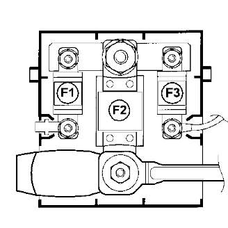
- F1 40A Fuse box in passenger compartment
- F2 – 400A – Power supply for the fuse box for the supply circuits, the starter and the starting system
- F3 – 40A – Injection computer power relay fuse.
Engine compartment
It is located under the hood on the left side
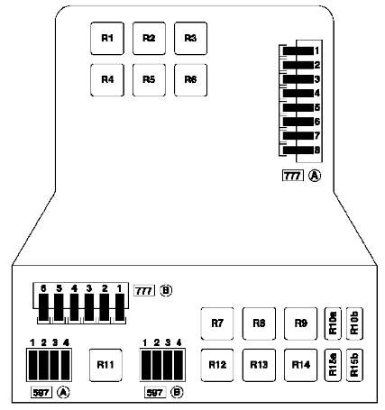
Relay description
- Air suspension relay R1
- R2 relay for engine operation for G9T and G9U engines in a 16-seat bus modification or for additional equipment
- R3 Relay for heated windshield
- R4 Not used
- R5 Not used
- R6 Not used
- R7 Relay for cooling fan 2 on vehicles with air conditioning
- R8 Not used
- R9 Auxiliary heating relay 3
- R10a Not used
- R10b Not used
- R11 Auxiliary heating relay 2
- R12 engine ECU relay
- R13 Auxiliary heating relay 1
- R14 Engine cooling fan relay 1 on vehicles with heating and air conditioning
- R15a air conditioning compressor relay
- R15b diesel heater relay
Description of fuses
Table A (777)
- 70A Passenger compartment fuse box power supply fuse, exterior lighting and direction indicator switch, ignition switch
- 30A Air conditioning control panel fuse
- 70A Passenger compartment fuse box power supply fuse, switch for exterior lighting of direction indicators
- Not used
- 70A Post Ignition 1 Relay Feed Fuse, Heated Rear Window Relay, Passenger Compartment Fuse Box
- 30A Air suspension relay fuse
- 70A Heated windshield relay fuse
- 60A ABS ECU power relay fuse
Table B (777)
- 70A Fuse for powering the pre-heater
- 50A Engine cooling electric fan relay 1, engine cooling electric fan low speed relay
- 30A Auxiliary heating relay 1
- 40A For ZD3 engine only: Engine cooling electric fan relay 2
- 70A Auxiliary heating relay 2 and 3
- 30A fuse relay for gearbox pump assembly
Table A (597)
- 20A Engine circuit fuse
- 10A Fuse for fuel pump relay
- Not used
- 25A ECU injection system
Table B (597)
- 30A Auxiliary heating relay 3
- 30A Auxiliary heating relay 2
- 30A Auxiliary heating relay 1
- 5A Contact plate supply fuse for additional equipment.