Komatsu PC14R-2 – fuse box
Komatsu PC14R-2 – fuse box diagram
Year of production:
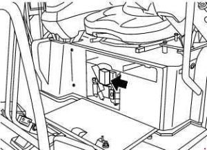
Fuse box
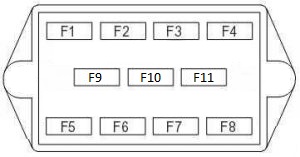
| Number | Amperes [A] | Description |
| 1 | 10 | Radio power supply |
| 2 | 30 | Engine stop solenoid supply;
Engine stop clock; Safety relay; Alternator excitation. |
| 3 | 10 | Fuel pump;
Work light. |
| 4 | 20 | High low speed switch;
PPC solenoid valve; Display power supply. |
| 5 | 15 | Horn |
| 6 | 15 | Windshield wiper;
Overhead lighting; Heating (for machine with cabin). |
| 7 | 10 | Optional equipment |
| 8 | 10 | Rotating light |
| 9 | – | Free |
| 10 | – | Free |
| 11 | – | Free |
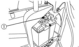
Main fuse
If the starter does not work when the ignition switch is turned to the ON position, the fuse (1) may have blown. Open the cover on the left side of the machine to check the fuse and replace it if necessary. The main fuse is located on the battery.