

Bobcat 325 – fuse box
Bobcat 325 – fuse box diagram
Year of production:
Fuse box
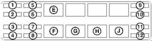
| Number | Amperes [A] | Description |
| 1 | – | – |
| 2 | 25 | Heater |
| 3 | 5 | Ignition |
| 4 | 25 | Fuel solenoid valve |
| 5 | 5 | Mat |
| 6 | 20 | Switch the power on |
| 7 | 25 | Alternator;
Heater. |
| 8 | 25 | ACD (included control device) |
| 9 | 25 | Controller |
| 10 | 25 | ACD (included control device) |
| 11 | 20 | The lights |
| 12 | 15 | Accessory plug |
| Relay | ||
| E. | Switchable power | |
| F. | Fuel solenoid valve | |
| G. | The lights | |
| H. | Glow plugs | |
| J. | Starter | |
The excavator is equipped with a 12 volt negative grounded electrical system. The electrical system is protected by fuses located under the excavator’s right side hatch (item 1). Fuses protect the electrical system in the event of an electrical overload. Before restarting the engine, determine the cause of the overload.
WARNING: Terminal and harness assignments for individual connectors will vary depending on vehicle trim level, model, and market.