

Renault Premium DXI450 – fuse box
Renault Premium DXI450 – fuse box diagram
Production year: 1996, 1997, 1998, 1999, 2000, 2001, 2002, 2003, 2004, 2005, 2006, 2007, 2008, 2009, 2010, 2011, 2012, 2013.
The cigarette lighter fuse (power socket) on the Renault Premium DXI450 is fuse F14 or 30 (depending on version) in the fuse box.
Fuse box
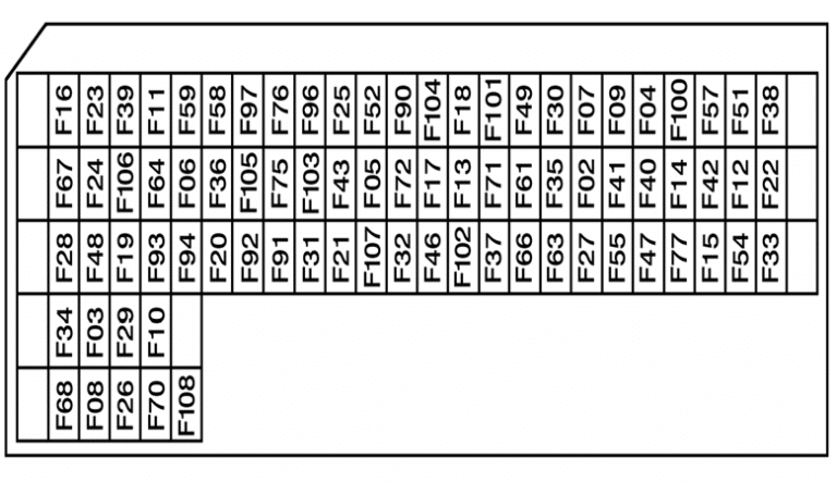
| Description | Number | Amperes [A] |
| Main information display;
Safety and authorization relay cab tilt; Cab tilt motor power relay. |
F03 | 7.5 |
| Main information display | F04 | 5 |
| Headlight washer pump motor | F05 | 30 |
| Main information display;
Tachograph. |
F06 | 5 |
| Vehicle management ECU | F07 | 5 |
| Main information display;
ECU engine immobilizer; ECU alarm; Door central locking ECU; Air production management ECU. |
F08 | 5 |
| ECU for pre-managementthe bodybuilder’s findings. | F09 | 5 |
| Air conditioning ECU | F10 | 30 |
| Hydraulic retarder control;
Electric retarder controller. |
F11 | 10 |
| Gear shift controller;
Automatic gearbox control unit. |
F12 | 15 |
| Management of lighting and signaling;
Windshield wiper motor; Time delay relay; Windshield washer pump motor; Windshield wiper drive motor. |
F13 | 20 |
| Lighter | F14 | 15 |
| Vehicle diagnostic socket;
Vehicle data download socket. |
F15 | 5 |
| Selection control;
The difference between the wheels – a lamp warning lockout; mechanism lock solenoid rear wheel differential; Pto engagement solenoid valve number 1; PTO engagement solenoid No. 2; PTO engagement solenoid No. 3; Interaxle differential; Lock solenoid valve. |
F 16 | 10 |
| Right traffic light | F17 | 10 |
| Electric horn;
Sound signal. |
F18 | 10 |
| Air conditioning controller | F19 | 5 |
| Radio set;
Alarm controller; Central door lock. |
F20 | 10 |
| ABS / EBS trailer socket | F21 | 20 |
| Single driver’s side overhead light;
Single passenger side top light; Overhead lighting (door); Lighting in the space of the staircase. |
F22 | 10 |
| Piloted axle lock angle sensor;
Piloted axle lock angle sensor; Air suspension controller; Steered axis controller. |
F23 | 5 |
| Fuel heater resistor # 2 | F24 | 20 |
| Power available(device in the warning pictogram
the “road” position); Power (lighting) available; Device in unlocked position warning light; Equipment warning lamp for lighting; 15-pin trailer socket. |
F25 | 10 |
| Power available (after ignition) | F26 | 15 |
| Window actuator | F27 | 20 |
| EBS braking management controller | F28 | 20 |
| Automatic transmission switch;
Built-in ECU management interface. |
F29 | 10 |
| Controller for lighting and signaling management | F30 | 30 |
| ECU cabin temperature control;
ECU alarm; Additional air-water heater; Additional air-air heater; Air conditioning ECU. |
F31 | 20 |
| Power available (after main switch) | F32 | 10 |
| Cab tilt motor | F33 | 30 |
| Built-in ECU management interface | F34 | 3 |
| Controller for lighting and signaling management | F36 | 10 |
| Voltage converter (24V / 12V – 15A)for an audio communication system;
Radio kit. |
F37 | 10 |
| Additional signal lights;
Warning light; Work light. |
F38 | 10 |
| Vehicle management ECU;
Defrost LH; Rear-view mirror resistor RH; Defrosting; Rear-view mirror resistor; Heated and rotating relay power rear view mirror; Defrost control relay the windscreen. |
F39 | 15 |
| Engine operation control;
Starter; Starting relay; Air preheating relay; Engine brake; Solenoid valve number 1; Exhaust brake solenoid; Range change solenoid; Solenoid valve controlling the engine distributor; Speed control solenoid engine cooling fan. |
F40 | 30 |
| Starter;
Starting relay; Engine brake 1 solenoid valve; Engine brake 2 solenoid valve; Exhaust brake solenoid; Range change solenoid; Solenoid valve controlling the distributor. |
F41 | 15 |
| Air preheating relay;
Regulating solenoid valve engine cooling fan speed. |
F42 | 10 |
| 24V power socket;
Automatic diagnostic socket gearbox. |
F43 | 15 |
| Rotary lamp No. 1;
Rotary lamp No. 2; Rotary lamp power supply relay. |
F46 | 15 |
| Air production management ECU | F47 | 7.5 |
| Holding the brake for steering;
EBS brake management ECU. |
F48 | 3 |
| Air suspension ECU;
Vehicle Power Management (ADR) ECU. |
F49 | 5 |
| Steered axle steered ECU | F51 | 5 |
| Automatic transmission switch;
ECU engine immobilizer; Cabin emergency stop controller; Vehicle controller; Post-ignition feed relay No. 1; After ignition feed relay No. 2; After ignition feed relay No. 3; Accessory power relay # 1; Accessory power relay # 2; Alternator circuit grounding relay (ADR); Alternator circuit pull resistor; Vehicle diagnostic socket. |
F52 | 10 |
| On-board management controller | F54 | 10 |
| Hydraulic retarder control | F57 | 10 |
| Cabin emergency stop controller;
Alternator circuit grounding relay (ADR). |
F58 | 3 |
| Preparation for On-Board Management (ECU);
Holding the brake to enable steering; Reversing lamp power relay. |
F59 | 10 |
| Voltage converter (24V / 12V)to the IT package. | F61 | 15 |
| 24V power socket | F63 | 15 |
| 15-pin trailer socket | F64 | 10 |
| Tool compartment lighting;
Front grille lighting; Electric roof vent motor. |
F66 | 10 |
| Gear shift controller;
Automatic gearbox control unit. |
F67 | 20 |
| Voltage converter (24 V / 12 V – 10 A) for an audio communication system;
Voltage converter (24 V / 12 V – 15 A) for an audio communication system; Voltage converter (24V / 12V) -12 and 24V integrated sockets; Refrigerator compartment; Auxiliary 24 V power socket. |
F68 | 20 |
| ABS / EBS trailer socket | F70 | 10 |
| Power available (after ignition) | F71 | 15 |
| High beam warning light;
Low beam LH. |
F72 | 10 |
| Power available(alternator information, engine running);
Heated left seat assembly; Left heated seat. |
F75 | 15 |
| Vehicle hour meter;
Additional air heater; Alternator circuit grounding relay (ADR); Additional solenoid valve air / water heater. |
F76 | 10 |
| Power available (after main switch) | F77 | 15 |
| Management of lighting and signaling ECU;
Rear fog lamp power relay; High beam power relay; Fog lamp power relay; Night lighting power supply relay; Fog lamp shutdown relay with the traffic lights on. |
F90 | 3 |
| Right-hand side marker light no. 1;
Right-hand side marker light no. 2; Left front / parking marker lamps; Right-hand side marker lamps No. 3; Right-hand marker lamps No. 4; Right rear / parking lights; Left position roof lights; Left marker lamps mounted on anti-glare stripes; Vehicle management ECU (ADR) power supply. |
F91 | 10 |
| Right front position / parking lights;
Left-hand side marker lamps No. 1; Left-hand marker lamps No. 2; Left-hand marker lamps No. 3; Left-hand side marker lamps No. 4; Left rear position lamps; Left position roof lights; Right-hand side marker light installed on anti-glare stripes. |
F92 | 10 |
| Power supply available (rear right-hand marker lamp (s);
15 pin trailer socket. |
F93 | 10 |
| Power supply available (rear left marker lamp (s);
15 pin trailer socket. |
F94 | 10 |
| Instruments and control of night lighting | F96 | 3 |
| Power available (night lighting) | F97 | 5 |
| Road warning lights;
Fog lights; Right warning lights; Left main beam headlights; Left dipped beam; Fog lights. |
F100 | 15 |
| Fog Lamp Warning Light;
Right rear fog light; Left rear fog light; 15 pin trailer socket. |
F101 | 10 |
| Main information display;
Right long range main beam; Left long range main beam. |
F102 | 10 |
| Power available (reversing information);
Reverse buzzer lock control; Reversing lamps; External horn; 15 pin trailer socket. |
F103 | 10 |
| Brake lights;
15 pin trailer socket. |
F104 | |
| Nitrogen oxides concentration sensor in gases;
AdBlue supply control pump module; Engine water circuit bypass solenoid. |
F107 | 10 |
| Additional air heater | F108 | 20 |
Relays
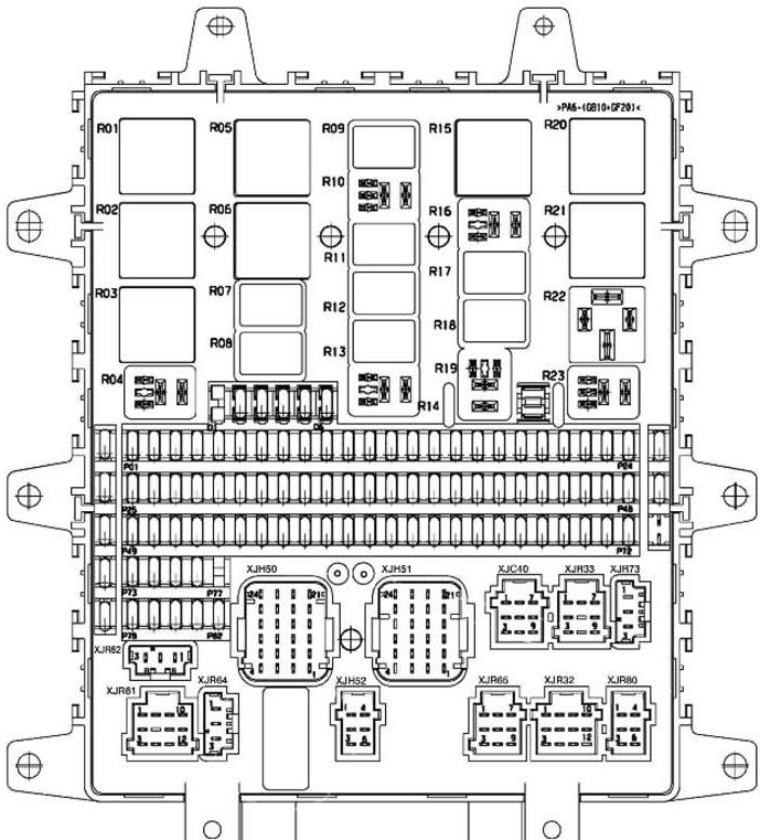
| Description | Amperes [A] | Number |
| After ignition, power relay No. 1 | 50 | R01 |
| After ignition, power relay No. 2 | 50 | R02 |
| After ignition, power relay No. 3 | 50 | R03 |
| Heated power relay irotating rearview mirror | 10 | R04 |
| Power relay controlled byalternator (engine running) | 20 | R05 |
| Right and left power relayside / parking and outline marker. | 20 | R06 |
| Turns on the nightlight power supply relay | 10 | R07 |
| High beam power relay | 10 | R08 |
| Alternator circuit grounding relay (ADR) | 10 | R09 |
| Additional heater power relay | 10 | R10 |
| Safety relay iauthorization to tilt the cabin | 10 | R11 |
| Side / Park Lamp Power Relay ileft and right markers
(trailer and bodybuilder) |
10 | R12 |
| Stop lamps feed relay | 10 | R13 |
| High beam power supply relay | 10 | R14 |
| Windshield wiper motor delay relay | 20 | R15 |
| Automatic transmission ECU supply relay | 10 | R16 |
| Relay actuation | 10 | R17 |
| Rear fog lamp power relay | 10 | R18 |
| Air suspension power relay | 10 | R19 |
| Vehicle and engine ECU power supply relay | 50 | R20 |
| Accessory power relay # 1 | 50 | R21 |
| Accessory power relay # 2 | 50 | R22 |
| Fog lamp power relay | 10 | R23 |
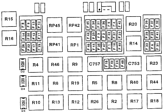
Type 2
| Chronometer | F1 |
| Back-up power (after the starter contact) | F1 |
| Seven-pin trailer socket (ABS) | F1 |
| Powering the “SERVICE” and “DANGER” control lamps | F1 |
| “ABS / ASR” Solenoid Relay (Left Front / Rear Right) | F1 |
| “ABS / ASR” Solenoid Relay (Front Right / Rear Left) | F1 |
| ABS emergency protection relay | F1 |
| “ABS / ASR” computing device | F1 |
| Electric relay that cuts off the retarder | F1 |
| On-board computer | F1 |
| Zero speed relay | F1 |
| Neutral position relay | F1 |
| Parking light, right | F2 |
| Right side light | F2 |
| Emergency power (for lighting) | F3 |
| Parking light, left | F3 |
| Light on the left | F3 |
| Power for trailer parking lights | F4 |
| Emergency power (for lighting) | F5 |
| Instrument panel illumination | F6 |
| Illumination of switches | F6 |
| Reserve | F7 |
| Fog lamp (or lanterns) | F8 |
| Fog lights | F9 |
| Right high beam headlamp | F10 |
| Left high beam headlamp | F11 |
| Left dipped beam headlamp | F12 |
| Right dipped headlight | F13 |
| Long-range floodlights | F14 |
| Stroke drive for wipers | F15 |
| Electronic tachograph | F15 |
| Brake light switch | F 16 |
| ” DELTA 2″ protection block for transmission | F 16 |
| Reversing lamps | F 16 |
| Daytime running lights relay | F 16 |
| Lock the oil level and temperature in the engine cooling system | F 16 |
| Brake lining wear signal relay | F 16 |
| Power supply for control panel indicator lamps | F 16 |
| Rearview mirror and windshield defrost switch | F 16 |
| Car Radio | F17 |
| Step-down transformer (telecommunication circuit) | F17 |
| Air conditioner circuit | F18 |
| Emergency stop switch “TBV” (RTMDR version) | F18 |
| “TBV” computing device | F18 |
| Automatic clutch computing device | F18 |
| Air heater (s) | F18 |
| Fuel filter heater | F19 |
| Turning on the lights | F20 |
| Roof hatch engine | F20 |
| Backup power supply (after the main switch) | F21 |
| Autonomous heater “D1LC” | F22 |
| Autonomous heater “D1LCC” | F22 |
| Autonomous heater “Thermo 90” | F22 |
| Driver’s light | F23 |
| Passenger light | F23 |
| Lower sofa ceiling | F23 |
| Top couch ceiling | F23 |
| Footrest lighting | F23 |
| Side drawer lighting | F23 |
| Engine window lifter controller | F24 |
| Passenger elevator glass motor | F24 |
| Control the tachograph clock | F25 |
| Buzzer | F26 |
| Stop signal | F27 |
| “ABS / ASR” computing device | F28 |
| Rotating mirror for defrosting, left | F29 |
| Rotary mirror with defrost, right | F29 |
| Timer for windshield defrosting | F29 |
| Power supply of additional control tachograph elements | F30 |
| Headlamp adjustment drives | F30 |
| Heated driver’s seat | F30 |
| Heated passenger seat | F30 |
| Lighter | F30 |
| Step-down transformer (to 12 V socket) | F30 |
| Reserve | F31 |
| Wiper drive motor | F32 |
| Glass washer pump | F32 |
| Headlight washer pump | F32 |
| Diagnostic socket | F33 |
| Suspension computing device (6 × 2/6 × 4) | F33 |
| Interrupter, direction indicator | F34 |
| Powering the memory of the car radio receiver | F34 |
| On-board computer | F34 |
| Autonomous heater “D1LC” | F34 |
| Autonomous heater “D1LCC” | F34 |
| Programmable auxiliary heater switch | F34 |
| Back-up power (after the starter contact) | F35 |
| Seven-pin trailer socket (ABS) | F36 |
| Left electric latch | F37 |
| Right electric latch | F37 |
| Reserve | F38 |
| Reserve | F39 |
| Reserve | F40 |
| Reserve | F41 |
| Automatic clutch computing device | F42 |
| Backup power (for neutral circuit) | F42 |
| Valve lighting | F43 |
| Work light (tractor) | F43 |
| Radiator grille lighting | F43 |
| Trailer power supply + 24 V | F43 |
| Cab tilt pump | F44 |
| General electrical switch | F45 |
| Central locking block | F45 |
| Engine heater switch | F46 |
| Fuel filter heater switch | F46 |
| Speed limiter computing device | F46 |
| Dot matrix display | F46 |
| Air heater (s) | F46 |
| Suspension computing device (4 × 2) | F47 |
| Remote Control Remote Control suspension | F47 |
| Rear axle airbag pressure sensor (6 × 2) | F47 |
| Reserve | F48 |
| “ITC” computing device | F49 |
Relay
- Power relay on RP1 contact
- Power relay after contact R2
- Oil pressure switch R4
- Park lamp relay R5
- Relay for additional comfort elements R6
- Light relay R8
- Fog lamp relay R9
- Fog lamp relay R10
- Dipped beam relay R11
- High beam relay R12
- Relay for long-range floodlights R13
- Brake light relay R14
- Relay for solenoid valves “ABS / ASR” (Front right / rear left) R15
- Relay for solenoid valves “ABS / ASR” (Front Left / Rear Right) R16
- ABS R17 emergency protection relay
- Relay for disconnecting the electric retarder R18
- Backup relay R19
- R20 mirror and windshield defroster relay
- Relay for headlamps R23
- Brake lining relay R26
- Backup relay R40
- R41 fuel heating relay
- Backup relay R42
- Backup relay R44
- RP45 cab tilt relay
- Auxiliary heater relay R46
- Headlight washer timing relay C753
- “EASY” horn С757
Additional items
The following relay and fuse elements may be located on the outside of the device:
- Auxiliary heater relay
- Anti-start relay
- Zero speed relay
- Neutral position relay
- Zero Speed Relay (Auto Clutch)
- Emergency protection relay “ITC”
- Hydraulic relay that cuts off the retarder
- Daytime running lights relay
- Windshield Defroster Relay (Time Delayed)
- Relay start
- Engine heater relay
- 25A Circuit breaker for direction indicators and alarm
- 25A Independent heating
- 25A On- board radio
- 25A Alarm
- 25A Central locking
Battery box
There may also be a high-power fuse block on the battery box cover.

| FM1 | 125A Cabin power supply |
| FM2 | 200A Electric truck lift |
| FM3 | 125A Engine air intake heater |
| FM4 | 40A Reserve |