

Toyota RAV4 XA40 and CA40 (2013-2019) – fuse box
Toyota RAV4 XA40 and CA40 (2013-2019) – fuse box diagram
Year of production: 2013, 2014, 2015, 2016, 2017, 2018, 2019.
The cigarette lighter fuse (power socket) on the Toyota RAV4 XA40 and CA40 is fuse 8 in the fuse box under the dashboard.
The cigarette lighter fuses (power outlets) on the Toyota RAV4 are fuses 9 and 18 in the instrument panel fuse box.
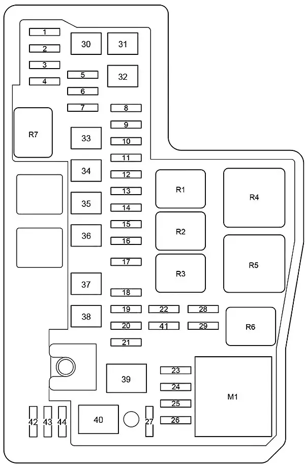
Engine compartment
location

Description
- Fuse and relay box
- Engine control unit
- Glow plug control unit
- Generator control unit
- From October 2015: Fan control unit
- Headlight wiper relay
- Transmission control unit
- Relay box
- Injector control unit
- Stepless valve lift controller
- Brake actuator
- Glow plug relay
- From Oct.2015: Fuel heater relay
Fuse and relay box
It is located on the left side of the engine compartment.

Type A

Description
| 1 | 20A – 2AR-FE: Multiport fuel injection system;
Sequential multiport fuel injection system; Fuses: “EFI NO.1”, “EFI NO.2”. |
| 25A – 3ZR-FE, 3ZR-FAE: Multiport fuel injection system;
Sequential multiport fuel injection system; Fuses: “EFI NO.1”, “EFI NO.2”. |
|
| 30A – Diesel: Multiport fuel injection system;
Sequential multiport fuel injection system; Gearbox control unit; Fuse: “EFI NO.3”. |
|
| 2 | 30A – Trailer connector |
| 3 | 10A – Steering lock |
| 4 | 10A – Air conditioning;
Instrument cluster; Intelligent entry and take-off system; Roof module. |
| 5 | 10A – Instrument cluster |
| 6 | 20A – 2AR-FE: Air flow sensor;
Fuel pump; Rear lambda probe. |
| Diesel: fuses: “EFI NO.1”, “EFI NO.2” | |
| 15A – 3ZR-FE, 3ZR-FAE: Multiport fuel injection system;
Sequential multiport fuel injection system. |
|
| 7.5A– From October 2015: 2WW: Multiport Fuel Injection System;
Sequential multiport fuel injection system. |
|
| 7 | 20A – Before October 2015: Starting system |
| 30A – From October 2015: Trunk door;
Instrument cluster; Double lock; Intelligent entry and start system; Fog lights; Windshield wipers and sprinklers; Headlights; Immobilizer; Interior lighting; Electric windows; Rear fog light; Seat belt indicator; Airbags; Boot system; Steering wheel lock; Anti-theft system; Tire pressure monitoring system; Wireless control system. |
|
| 8 | 30A – Starting system |
| 30A – Starting system | |
| 9 | 30A – Audio system |
| 30A– From October 2015: Audio system | |
| 10 | 10A – Multipoint fuel injection system;
Sequential multiport fuel injection system. |
| 30A – From October 2015: 2WW: Fuel pump | |
| 11 | 10A – Before Oct. 2015: Anti-theft system |
| 30A – From October 2015 (without telematics system): Start-Stop system | |
| 7.5A – From October 2015: Telematics system | |
| 12 | 15A – Multipoint fuel injection system;
Sequential multiport fuel injection system; Fuses: “METER”, “IGN”, “A / B”. |
| 13 | 7,5A – Starting system;
Fuse: “IG2”. |
| 14 | 7.5A – Current sensor;
Generator. |
| 15 | 10A – Horn, horn |
| 16 | 25A – Diesel: Multiport fuel injection system;
Sequential multiport fuel injection system. |
| 20A – From October 2015: 3ZR-FAE: Takeoff System | |
| 10A – From October 2015: Anti-theft system | |
| 17 | 30A – Fuses: “DOME”, “ECU-B NR 1”, “RADIO” |
| 18 | 5A – Wiper switch;
Current sensor; Multipoint fuel injection system; Sequential multiport fuel injection system. |
| 19 | 10A – 3ZR-FE: Air flow sensor;
VSV; ACIS VSV; Rear oxygen sensor; Multipoint fuel injection system; Sequential multiport fuel injection system. |
| 10A – 3ZR-FAE: Multiport fuel injection system;
Sequential multiport fuel injection system. |
|
| 10A – 2AR-FE: Air flow sensor;
VSV; ACIS VSV. |
|
| 10A – 1AD-FTV: Air flow sensor;
Oil valve; EDU; ADD FUEL VLV; EGR; Start-stop system; Glow plugs. |
|
| 10A – 2AD-FTV, 2AD-FHV: EDU;
ADD FUEL VLV; EGR; Air flow sensor; VNT E-VRV. |
|
| 7.5A – From October 2015: 2WW:
Multiport fuel injection system; Sequential multiport fuel injection system. |
|
| 20 | 10A – 3ZR-FAE: Air flow sensor;
VSV; ACIS VSV; Rear oxygen sensor; Start-stop system. |
| 10A – 2AR-FE: Multiport fuel injection system;
Sequential multiport fuel injection system. |
|
| 10A – 3ZR-FE, 2AD-FTV, 2AD-FHV: Air flow sensor | |
| 15A – From October 2015: 2WW: Multiport Fuel Injection System;
Sequential multiport fuel injection system. |
|
| 21 | 10A – Left main beam light;
High beam indicator. |
| 22 | 10A – Right main beam light |
| 23 | 7.5A – Multipoint fuel injection system;
Sequential multiport fuel injection system; Gearbox control unit. |
| 20A – From October 2015: 2WW: Multiport fuel injection system;
Sequential multiport fuel injection system. |
|
| 24 | – |
| 25 | – |
| 26 | 20A – Radio and audio system |
| 27 | 10A – Body electric control unit;
Wireless control system; Steering wheel position sensor; Central lock; Clock; Electric tailgate; Tire pressure monitoring system. |
| 28 | 10A – Interior lighting;
Luggage compartment lighting; Personal lighting. |
| 29 | 10A H-LP LH-LO – Until October 2015:
Halogen bulbs: Dipped beam; Headlight range adjustment; From October 2015: Left dipped beam; Headlight range adjustment. |
| 15A H-LP LH-LO – before October 2015: HID:
Left dipped beam; Headlight range control. |
|
| 30 | 10A H-LP RH-LO – Until October 2015:
Halogen bulbs: Right low beam; From October 2015: Right low beam. |
| 15A H-LP RH-LO – before October 2015:
HID: Right dipped beam. |
|
| 31 | – |
| 32 | – |
| 33 | – |
| 34 | – |
| 35 | 50A FUEL HTR – From October 2015: 2WW:
Fuel heating. |
| 36 | 40A BBC – Start-stop system |
| 37 | 30A VLVMATIC -VALVEMATIC system |
| 50A – From October 2015: 2WW:
ABS; Cruise control; Hill Descent Assist; Hill Start Assist; Start / Stop system; Panoramic vision system; Dynamic cruise control radar; TRC; VSC. |
|
| 38 | 30A – VSC, ABS |
| 39 | 50A – VSC, ABS |
| 40 | 50A – Fuses: “H-LP RH-LO”, “H-LP LH-LO”, “H-LP RH-HI”, “H-LP LH-HI” |
| 41 | 80A – Glow plugs |
| 42 | 80A – Electric power steering |
| 43 | 120A ALT – Before October 2015:
Gas: Fuses: “STOP”, “S / ROOF”, “AM1”, “OBD”, “D / L NO.2”, “FOG RR”, “D / L BACK”, “P / OUTLET NO.1″, ” DOOR D “,” DOOR P / P “,” DOOR P / L “,” WIP RR “,” WSH “,” INDICATOR “,” WIP PRZ “,” SFT LOCK-ACC “, P / OUTLET NO. 2” “, ACC” “, PANEL” “, TAIL” “, D / L NO.2” “, EPS-IG” “, ECU-IG NO.1” “, ECU -IG NO.2” “, HTR-IG” “, S-HTR LH” “, S-HTR RH” “, IGN” “, A / B” “, METER” “, ECU-IG NO.3” |
| 140A ALT -Before October 2015:
Diesel, (3ZR-FAE from April 2015): From October 2015: Except 2WW: Fuses: “ABS NO.1”, “ABS NO.2”, “RDI FAN”, “FAN NO.” 1 “”, S / HTR R / L “”, DEICER “”, FOG FR “”, S / HTR R / R “”, CDS FAN “”, FAN NO.2 “”, HTR “”, STV HTR ” , “TOWING-ALT”, “HWD NR 1”, “HWD NR 2”, “H-LP CLN”, “DRL”, “PTC HTR NR 1”, “PTC HTR NR 2”, “PTC HTR NR 3” , DEF “, NOISE FILTER”, STOP “, S / ROOF, AM1, OBD, D / L, NO.2, MGŁA, RR, D / L BACK” “, R / OUTLET NO.1” “, DOOR D” “, P / P DOOR “”, P / L DOOR “”, WIP RR “”, WSH “”, INDICATOR “”, WIP FR “,” SFT LOCK-ACC “,” P / OUTLET NO. 2 “,” ACC “, “PANEL”, “TAIL”, “D / L NO.2”, “EPS-IG”, “ECU-IG NO.1” “, ECU-IG NO.2” “, HTR-IG” “, S- HTR LH “”, S-HTR RH “”, IGN “”, “A / B” “METER” “, ECU-IG NO 0.3” |
|
| Relay | |
| R1 | Engine control unit |
| R2 | Ignition |
| R3 | Diesel:
Engine control unit; Gas: Fuel pump; 2WW: p Fuel pump. |
| R4 | Before October 2015:
Lights; From October 2015: Dimmer. |
| R5 | Engine control unit |
| R6 | Before October 2015:Dimmer |
| From October 2015: Except for 2AR-FE:
Headlights; 2AR-FE: Headlamps – Daytime running lights. |
|
Type B
Description
| 1 | 20A – Audio system |
| 2 | 10A – body ECM;
Wireless control system; Steering wheel position sensor; Clock; Electric tailgate; Tire pressure monitoring system; Driver position memory. |
| 3 | 10A – Interior lighting;
Personal lighting; Luggage compartment lighting; Individual mirror lighting. |
| 4 | – |
| 5 | 20 – Heated brush rest area |
| 6 | – |
| 7 | 7.5A – Fog light;
Fog light indicator. |
| 8 | 30A – Audio system |
| 9 | 30A– Starting system |
| 10 | 20A – Multiport fuel injection system;
Sequential multiport fuel injection system; Fuses: “EFI NO.1”, “EFI NO.2”. |
| 11 | – |
| 12 | 15A – Multipoint fuel injection system;
Sequential multiport fuel injection system; Fuses: “METER”, “IGN”, “A / B”. |
| 13 | 10A – Instrument cluster |
| 14 | 7,5A – Starting system;
Fuse: “IG2”. |
| 15 | 10A – Air conditioning;
Instrument cluster; Front passenger classification system; Intelligent entry and start system. |
| 16 | 10A – Steering lock |
| 17 | 30A – Fuses: “DOME”, “ECU-B NR 1”, “RADIO” |
| 18 | 10A – Sound signal |
| 19 | 10A – Multipoint fuel injection system;
Sequential multiport fuel injection system. |
| 20 | 20A – Air flow sensor;
Fuel pump; Rear lambda probe. |
| 21 | 7.5A – Current sensor |
| 22 | 10A – Heated mirrors;
Multipoint fuel injection system; Sequential multiport fuel injection system. |
| 23 | 10A – Air flow sensor;
VSV; ACIS VSV. |
| 24 | 10A – Multipoint fuel injection system;
Sequential multiport fuel injection system. |
| 25 | 10A – Left main beam light;
High beam indicator. |
| 26 | 10A – Right main beam light |
| 27 | – |
| 28 | 10A – Left dipped beam |
| 29 | 10A – Right dipped beam |
| 30 | 30A – Cooling fan |
| 31 | 50A – Air conditioner |
| 32 | 50A – Daytime running lights;Fuses: “H-LP RH-LO”, “H-LP LH-LO”, “H-LP RH-HI”, “H-LP LH-HI”. |
| 33 | 30A – Auxiliary heater |
| 34 | Auxiliary heater |
| 35 | 30A – Rear window heating;
Fuse: “MIR HTR”. |
| 36 | 30A – VSC |
| 37 | 30A – Cooling fan |
| 38 | 50A – VSC |
| 39 | 80A EPS – Electric power steering |
| 40 | 120A ALT – Fuses: “ABS NO 1”, “ABS NO 2”, “PTC HTR NO 1”, “PTC HTR NO 2”, “DEICER”, “HTR”, “RDI FAN”, “CDS FAN“ ”, FOG FR “”, “DEF” |
| 41 | 5A – Wiper switch;
Rain sensor. |
| 42 | 10A – Spare fuse |
| 43 | 20A – Spare fuse |
| 44 | 30A – Spare fuse |
| M1 | Daytime running light module |
| Relay | |
| R1 | Engine control unit |
| R2 | Ignition |
| R3 | Fuel pump |
| R4 | Starter |
| R5 | Headlights |
| R6 | Engine control unit |
| R7 | Heated rear window |
Relay box
It is marked with the number 8 in the diagram. It is located on the right side of the engine compartment.

Type A

Description
| 1 | 5A – Daytime running lights |
| 2 | 30A – Trailer connector |
| 3 | 7.5A – Fog light;
Fog light indicator. |
| 4 | 10A – Noise filter |
| 5 | 25A – Auxiliary heater |
| 6 | 10A – From October 2015:
Heated rear seat |
| 7 | 20A – Heated brush rest area |
| 10A – From October 2015:
Heated rear seat |
|
| 8 | From October 2015: Diesel:
Cooling fan |
| 9 | – |
| 10 | 5A – From October 2015: Diesel:
Cooling fan |
| 11 | – |
| 12 | – |
| 13 | 10A – Heated mirrors;
Multipoint fuel injection system; Sequential multiport fuel injection system. |
| 14 | – |
| 15 | – |
| 16 | – |
| 17 | 50A – 600W, 840W:
Auxiliary heater |
| 30A – 330W: Auxiliary heater | |
| 18 | 50A – 840W: Auxiliary heater |
| 30A – 330W: Auxiliary heater | |
| 19 | 50A – 840W: Auxiliary heater |
| 30A – 330W: Auxiliary heater | |
| 20 | 30A – Cooling fan |
| 40A – From October 2015: 2WW: Cooling fan | |
| 50A – from October 2015: Trailer + Diesel: Cooling fan | |
| 21 | 30A– Cooling fan |
| 40A – From October 2015: 2WW: Cooling fan | |
| 50A – from October 2015: Trailer + Diesel: Cooling fan | |
| 22 | 50A – Air conditioner |
| 23 | 30A – Rear window heating;
Fuse: “MIR HTR”. |
| 24 | 50A – Heated windscreen |
| 25 | 30A – Headlight cleaners |
| 26 | 50A – Heated windscreen |
| Relay | |
| R1 | Cooling fan |
| R2 | Front fog lamp |
| R3 | Sound signal |
| R4 | Heater |
| R5 | Daytime running lights |
| R6 | Cooling fan |
| R7 | Cooling fan |
| R8 | Heated rear window |
| R9 | Auxiliary heater |
| R10 | Auxiliary heater |
| Heated windscreen | |
| R11 | Auxiliary heater |
| Heated windscreen | |
| R12 | Stop lights |
| R13 | Starter |
| R14 | Heated brush rest area |
| Heated steering wheel | |
| Heated area of the brush backrest;
Heated steering wheel. |
|
| AND | |
| R15 | From October 2015: Trailer + Diesel:
Cooling fan, Heated rear seat |
| R16 | From October 2015: Heated rear seat |
| B | |
| R17 | From October 2015: trailer + Diesel:
Cooling fan; Heated windscreen washer nozzles. |
| R18 | Starter |
| C. | |
| R19 | 330W: Auxiliary heater |
| 600W: Auxiliary heater | |
| R20 | Auxiliary heater |
Type B

Description
| R1 | Front fog lamps |
| R2 | Air conditioning compressor clutch |
| R3 | PTC heater |
| R4 | – |
| R5 | Horn |
| R6 | Electric cooling fan |
| R7 | PTC heater |
| R8 | Electric cooling fan |
| R9 | Starter |
| R10 | Electric cooling fan |
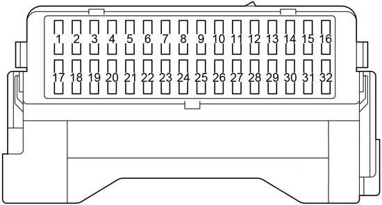
Passenger compartment
location
System of electronic control units
LHD (Left Hand Drive)

RHD (right hand drive)

Description
- LHD: Interior Lighting Relay (DOME CUT)
- Headlamp range control unit
- Fuse box / body ECM
- Steering lock actuator
- Power steering control unit
- Relay box
- Navigation control unit
- Four-wheel drive control unit
- Parktronic control unit (distance warning)
- Driver assistance systems control unit
- Gateway Lockout
- Wiper relay
- Start-Stop system control unit
- Gear selector control unit
- Airbag control unit
- Distribution connector
- Air conditioner amplifier
- Distribution connector
- RHD: Double door lock relay
Fuse box
It is located under the dashboard. In the diagram, this field is indicated at number 3.

Description
| 1 | – |
| 2 | 7.5A – brake lights |
| 3 | 10A – Hatch, sunroof |
| 4 | 5A – Fuses: “IG1 NO.1”, “IG1 NO.2”, “IG1 NO.3”, “ACC” |
| 5 | 7.5A – diagnostic connector |
| 6 | 20A – Before October 2015:
Central lock; Body ECU. |
| 7 | 7.5A – Rear fog light |
| 8 | 10A – Central locking (tailgate) |
| 9 | 15A – Socket (cigarette lighter) |
| 10 | 20A – Driver’s side window |
| 11 | 20A – Rear right power window |
| 12 | 20A – Rear left power window |
| 13 | 15A – Rear wiper |
| 14 | 15A – Windshield washer;
Rear window washer. |
| 15 | 7.5A – Reversing lamps;
Automatically dimming interior mirror; Blind spot monitor. |
| 16 | 25A– Windshield wiper |
| 17 | 5A – Lock the gear lever |
| 18 | 15A – Socket |
| 19 | 7.5A – Sockets, audio system, electric mirrors, body control unit, clock, current sensor |
| 20 | 7.5A – VSC OFF switch;
Instrument cluster; BSM circuit breaker; All-wheel drive switch; Switch for heating the brush backrest area; Multipoint fuel injection system; Sequential multiport fuel injection system; Parking assist systems; Seat heating switches, sockets; Door drive, trunk switch; Air conditioning control unit; Rear window heated switch; Audio system; Steering wheel buttons; Cup holder lighting. |
| 21 | 10A – Side light;
Number plate lighting; Fog light. |
| 22 | 20A – From October 2015:
Central lock; Body ECU. |
| 23 | 5A – Power steering |
| 24 | 10A – All-wheel drive (dynamic torque control);
Steering position sensor; Instrument cluster; Gear selector. |
| 25 | 5A – body ECU;
Wireless control system; Gear selector lock; Intelligent entry and start system; Sunroof; Audio system; Tailgate actuator; Tire pressure monitoring system; Blind spot monitoring system (blind spot monitor); Lane Keeping Assist, Power Assist (LDA). |
| 26 | 7.5A – Air conditioning;
Heated rear window. |
| 27 | 10A – Left heated seat |
| 28 | 10A – Heated right seat |
| 29 | 7.5A– Fuel pump, multiport fuel injection system;
Sequential multiport fuel injection system; Brake lights; Steering wheel lock. |
| 30 | 7.5A – Airbags;
Front passenger classification system. |
| 31 | 5A – Instrument cluster |
| 32 | 7.5A – Generator;
ABS / VSC; Heating the area of the remaining brushes; Brake lights. |
Additional fuses are attached to the other side of the device.

Description
- 30A P / SEAT F / L – Electric left seat
- 30A PBD – electric rear hatch
- 30A P / SEAT F / R – Electric right seat
- 30A P / W-MAIN – Front window lifters, window lifter control unit.
Relay box

Description
| R1 | LHD : Anti-Theft System (S-HORN); RHD : Interior lighting (DOME CUT). |
| R2 | Rear fog light (FOG RR) |
Additional items

Description
- Sunroof control unit
- Receiver for central locking and tire pressure monitoring systems, Tire pressure monitoring system control unit
- Central locking receiver
- Phone transceiver
- Parking assist control unit
- Right sensor for monitoring the blind spot
- Door control unit
- Left sensor of the blind spot monitor
- Fuel pump control unit
- Distribution connector
- Sound amplifier