

Bobcat S185 – fuse box
Bobcat S185 – fuse box diagram
Year of production:
Fuse box
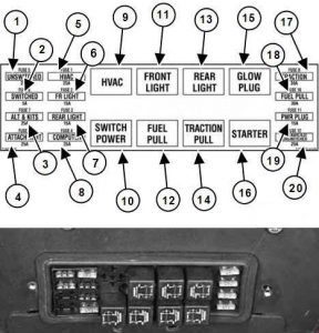
| Number | Amperes [A] | Description |
| 1 | 25 | Horn not connected |
| 2 | 5 | ACS / AWS / SJC with switch |
| 3 | 25 | Backup alternator and accessories alarm |
| 4 | 25 | Attachments |
| 5 | 25 | Heater and air conditioning |
| 6 | 15 | Front and marker lamps |
| 7 | 15 | Rear lights |
| 8 | 25 | Bobcat controller |
| 17 | 30 | Traction |
| 18 | 30 | Fuel cut-off |
| 19 | 15 | Power plug |
| 20 | 25 | ACS / AWS / SJC without switch |
| Relay | ||
| 9 | Heating and air conditioning | |
| 10 | Power switch | |
| 11 | Front and marker lamps | |
| 12 | Fuel cut-off | |
| 13 | Rear lights | |
| 14 | Traction | |
| 15 | Glow plugs | |
| 16 | Starter | |
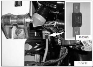
The charger has a negative grounded 12 volt alternator charging system. The electrical system is protected by fuses located in the cab on the control panel and a 100 amp main fuse in the engine compartment on the left side of the engine, under the air filter. Fuses protect the electrical system in the event of an electrical overload. Before restarting the engine, determine the cause of the overload.
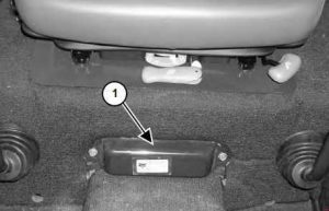
The electrical system is protected against overload by fuses and relays located under the fuse panel cover (item 1). Inside the cover there is a sticker showing the location and the amperage.
Remove cover to check or replace fuses.
WARNING: Terminal and harness assignments for individual connectors will vary depending on vehicle trim level, model, and market.