

Ford E-150 (2009-2015) – fuse and relay box
Fuse and Relay Box Diagrams – Ford E-150
Applies to vehicles manufactured in the years:
2009, 2010, 2011, 2012, 2013, 2014, 2015.
Diagram of the fuse box in the passenger compartment
The fuse panel is located on the left side of the brake pedal and is mounted on the lower left cover panel. Remove the fuse panel cover to access the fuses.
To remove the fuse, use the fuse puller on the inside of the fuse panel cover.
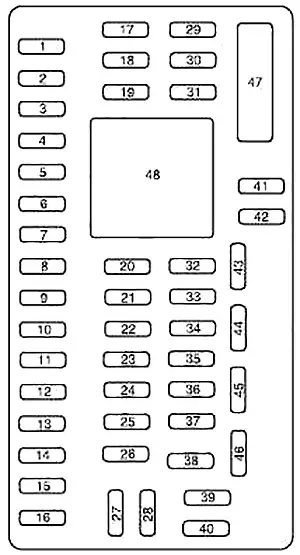
| Number | Amperes [A] | Description |
|---|---|---|
| 1 | thirty | 2013-2015: B + inverter |
| 2 | 15 | Not used (spare) |
| 3 | 15 | Not used (spare) |
| 4 | thirty | Not used (spare) |
| 5 | 10 | Passenger compartment fuse panel (SPDJB), brake shift lock |
| 6 | 20 | Direction indicator, hazard lights, brake lights |
| 7 | 10 | Left low beam |
| 8 | 10 | Right low beam |
| 9 | 15 | Courtesy lamps |
| 10 | 15 | Backlight switch |
| 11 | 10 | Not used (spare) |
| 12 | 7.5 | Not used (spare) |
| 13 | 5 | Mirrors |
| 14 | 10 | 2010-2015: SYNC, Navigation module (GPS) |
| 15 | 10 | Not used (spare) |
| 16 | 15 | Not used (spare) |
| 17 | 20 | Locks |
| 18 | 20 | Not used (spare) |
| 19 | 25 | Not used (spare) |
| 20 | 15 | Diagnostic connector (except for the disassembled housing) |
| 21 | 15 | Not used (spare) |
| 22 | 15 | Park lamps, license plate lamps |
| 23 | 15 | Traffic lights |
| 24 | 20 | Horn (except under the stripped chassis) |
| 25 | 10 | Lighting in demand |
| 26 | 10 | Cluster (except without housing) |
| 27 | 20 | Ignition switch power |
| 28 | 5 | Mute the sound (start) |
| 29 | 5 | Cluster (except without housing) |
| 30 | 5 | Not used (spare) |
| 31 | 10 | Not used (spare) |
| 32 | 10 | Constraints module |
| 33 | 10 | Trailer brake controller |
| 34 | 5 | Not used (spare) |
| 35 | 10 | Rear parking aid (2009-2014), Rear video camera (2009-2014), Section / start |
| 36 | 5 | Passive radio frequency module of the anti-theft system |
| 37 | 10 | Air conditioning, Disassembled IP # 1 chassis, commissioning / commissioning |
| 38 | 20 | Not used (spare) |
| 39 | 20 | Radio, navigation (2009-2014) |
| 40 | 20 | 2009-2014: Amplifier |
| 41 | 15 | Radio, switch illumination, rear view camera mirror, inverter (2013-2015) |
| 42 | 10 | Upfitter switch |
| 43 | 10 | Ceiling console, housing without IP1 insulation |
| 44 | 10 | Auxiliary battery relay / Trailer tow battery charger relay |
| 45 | 5 | Wipers, Undercarriage Exposed Engine Connector 3 |
| 46 | 7.5 | Passenger airbag deactivation indicator |
| 47 | thirty | Circuit breaker: Windows accessory delay |
| 48 | Delayed accessory | |
Diagram of the fuse box in the engine compartment
The power distribution box is located in the engine compartment. The distribution box contains high-current fuses to protect the vehicle’s main electrical systems from overload.
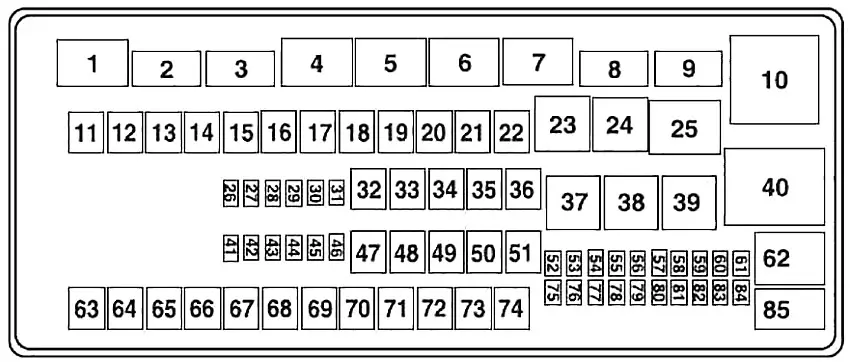
| Number | Amperes [A] | Description |
|---|---|---|
| 11 | – | Not used |
| 12 | 40 | Modified vehicle and chassisless start / take off |
| 13 | thirty | Starter solenoid relay |
| 14 | 40 | Start the start relay |
| 15 | 40 | Modified vehicle battery and chassis battery removed |
| 16 | 50 | Auxiliary air conditioning blower |
| 17 | 50 | Auxiliary battery power (2009-2010), trailer tow battery charge, trailer tow car park power supply |
| 18 | thirty | Electric trailer brake, trailer brake controller |
| 19 | thirty | Upfitter # 1 |
| 20 | thirty | Upfitter # 2 |
| 21 | 50 | 2009-2010: IDM relay / FICM relay (only diesel engine) |
| 22 | – | Not used |
| 26 | – | Not used |
| 27 | – | Not used |
| 28 | 20 | Backup lamp |
| 29 | 10 | Air conditioning clutch |
| 30 | 10 | Brake on / off switch |
| 31 | 10 | Cluster battery (chassis only with shell stripped), IDM / FICM coil (diesel only (2009-2010)) |
| 32 | 50 | Blower motor |
| 33 | 40 | ABS pump |
| 34 | 20 | Disassembled chassis horn |
| 35 | 40 | Powertrain control module (PCM) relay |
| 36 | 20 | Ignition switch (chassis only with cover removed) |
| 41 | 10 | 2009-2010: Charging (diesel only) |
| 42 | 15 | Diagnostic connector (truncated chassis) |
| 43 | 20 | Fuel pump |
| 44 | 10 | Upfitter # 3 |
| 45 | 15 | Upfitter # 4 |
| 46 | 10 | PCM holds power, canister vent, PCM relay coil |
| 47 | 40 | ABS coil |
| 48 | 20 | Trailer tow stop lamp / turn signal |
| 49 | thirty | Wiper motor |
| 50 | – | Not used |
| 51 | 20 | Cross-section |
| 52 | 10 | Undercarriage removed and modified vehicle start / start relay coil |
| 53 | 10 | ABS start / start feed |
| 54 | 10 | Fuel pump relay coil |
| 55 | 10 | 2009-2010: ECM / PCM (diesel only) |
| 56 | 20 | 2009-2010: Diesel conditioning module (DFCM) (diesel engine only) |
| 57 | 20 | Trailer tow lamp |
| 58 | 15 | Trailer tow reversing lamp |
| 59 | – | Not used |
| 63 | thirty | Charging the battery for towing a trailer |
| 64 | – | Not used |
| 65 | 20 | Power point 2 (glove box) |
| 66 | 20 | Power Point 3 (Left B Pillar) |
| 67 | 20 | Power point 1 (instrument panel) |
| 68 | 50 | A modified vehicle |
| 69 | – | Not used |
| 70 | thirty | Worn undercarriage |
| 71 | – | Not used |
| 72 | 20 | Cigarette lighter / Power point |
| 73 | – | Not used |
| 74 | thirty | Electric seat |
| 75 | 20 | Vehicle power 1, power of the powertrain control module |
| 76 | 20 | Vehicle power 2, powertrain control module – Emission related powertrain components |
| 77 | 10 | Vehicle power 3, powertrain control module – general powertrain components |
| 78 | 15 | Vehicle Power 4, Fuel Pump Relay Coil, Ignition Coil (Diesel (2009-2010) Only) |
| 79 | 10 | Vehicle power 5, gearbox |
| 80 | 10 | Cluster startup / startup (chassis only with disassembled housing) |
| 81 | 15 | IDM logic (diesel only) |
| 82 | – | Not used |
| 83 | – | (diode) |
| 84 | – | Not used |
| 60 | Integrated Start One Touch (OTIS) | |
| 61 | 2009-2011: Auxiliary battery | |
| 83 | Fuel pump | |
| 1 | Powertrain control module (PCM) | |
| 2 | Starter solenoid | |
| 3 | Mat | |
| 4 | Charging the battery for towing a trailer | |
| 5 | Fuel pump | |
| 6 | Trailer tow lamp | |
| 7 | Upfitter # 4 | |
| 8 | Upfitter # 3 | |
| 9 | Modified vehicle and chassisless start / take off | |
| 10 | 2009-2010: Fuel injector control module (FICM) / (IDM) (diesel engine only) | |
| 23 | Air conditioning clutch | |
| 24 | Horn Relay (Truncated Landing Gear) | |
| 25 | Run / start | |
| 37 | Trailer tow stop / left turn signal | |
| 38 | Trailer tow stop / right turn signal | |
| 39 | Backup lamp | |
| 40 | Blower motor | |
| 62 | Upfitter # 2 | |
| 85 | Upfitter # 1 | |