Ford F-750 (2016-2020) – fuse and relay box
Diagrams of fuse and relay boxes – Ford F-750
Applies to vehicles manufactured in the years:
2016, 2017, 2018, 2019, 2020.
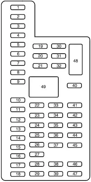
Diagram of the fuse box in the passenger compartment
The fuse panel is located in the passenger footwell. Pull the fuse panel cover towards you to remove it. When the panel clips are unhooked, the panel can fall easily.

| Number | Amperes [A] | Description |
|---|---|---|
| 1 | thirty | Left windshield motor |
| 2 | 15 | Upfitter relay # 4 |
| 3 | thirty | Right windshield motor |
| 4 | 10 | Internal lamps |
| 5 | – | – |
| 6 | – | – |
| 7 | 7.5 | Mirror power switch |
| 8 | – | – |
| 9 | 10 | Upfitter relay # 3 |
| 10 | 10 | Customer access for commissioning / accessories |
| 11 | 10 | Ford telematics battery power supply |
| 12 | 15 | Indoor lighting |
| 13 | 15 | Right turn lamps and brake lamps |
| 14 | 15 | Left turn lamps and brake lamps |
| 15 | 15 | Center high mounted brake light, reversing lights |
| 16 | 10 | Right low beam headlight |
| 17 | 10 | Left headlight dipped beam |
| 18 | 10 | Wake up powertrain control module, brake shift lockout |
| 19 | – | – |
| 20 | 20 | Electric door locks |
| 21 | 10 | Brake on / off switch |
| 22 | 20 | Horn |
| 23 | 15 | Instrument cluster |
| 24 | 15 | Diagnostic connector, power folding mirrors relay, steering wheel control module, remote keyless entry |
| 25 | – | – |
| 26 | 5 | Steering wheel control module |
| 27 | – | – |
| 28 | 15 | Ignition switch |
| 29 | 20 | GPS module, Radio, SYNC |
| 30 | 15 | Park lamps, trailer tow lamp park lamp relay coil |
| 31 | 5 | Customer Trailer Brake On / Off Switch |
| 32 | 15 | Delayed accessory power supply, driver and passenger door lock switch illumination, 11 Ov power inverter module, telescopic mirror switch |
| 33 | – | – |
| 34 | 10 | Run / run translator auxiliary module |
| 35 | 5 | Towing / Towage / Take-off |
| 36 | 10 | Fuel tank select switch |
| 37 | 10 | Auxiliary heater |
| 38 | 10 | Accessory delayed power supply, AM / FM basic radio |
| 39 | 15 | Left and right headlight main beam |
| 40 | 10 | Rear parking lamps, marker lamps |
| 41 | – | – |
| 42 | 5 | Ford telematics run / start |
| 43 | 10 | Power Distribution Box / Accessory Fuses, Wiper Relay Coil |
| 44 | 10 | Customer access upfitter switch power supply, auxiliary gear translator module / accessory sensor; |
| 45 | – | – |
| 46 | 10 | Air conditioning module |
| 47 | 15 | Fender turn signal lamps |
| 48 | thirty | Circuit Switch: Power Window Switch (Crew Cab) |
| 49 | Delayed power of accessories | |
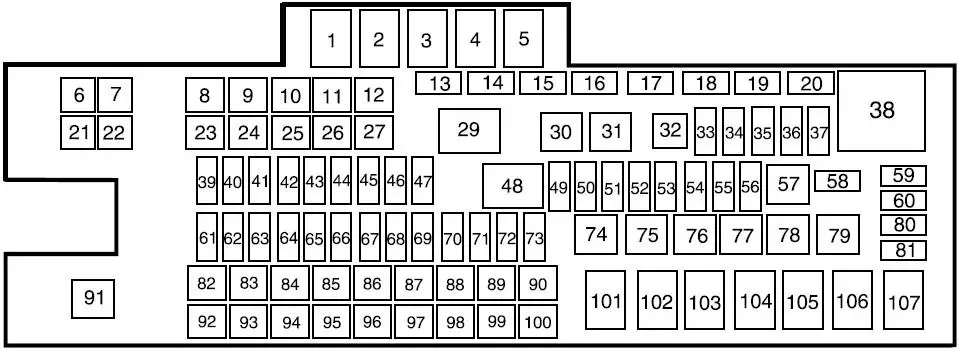
Diagram of the fuse box in the engine compartment
The power distribution box is located in the engine compartment.
| Number | Amperes [A] | Description |
|---|---|---|
| 6 | – | – |
| 7 | – | – |
| 8 | 20 | Air passenger seat compressor |
| 9 | – | – |
| 10 | – | – |
| 11 | – | – |
| 12 | – | – |
| 13 | – | Resistor: Terminator (120 ohms) |
| 14 | – | – |
| 15 | – | – |
| 16 | – | – |
| 17 | – | – |
| 18 | – | – |
| 19 | 10 | Brake on / off isolation relay |
| 20 | – | – |
| 21 | – | – |
| 22 | thirty | Electric brake controller for trailer towing |
| 23 | 40 | Blower motor |
| 24 | – | – |
| 25 | thirty | Wipers |
| 26 | thirty | Trailer tow lamps |
| 27 | 25 | Urea heaters (diesel engine) |
| 28 | – | – |
| 32 | – | – |
| 33 | 20 | Vehicle power 1 |
| 34 | 20 | Vehicle power 2 |
| 35 | 10 | Vehicle power 3 |
| 36 | 20 | Vehicle power 4 |
| 37 | 10 | Vehicle power 5 (diesel engine) |
| 39 | – | – |
| 40 | 15 | Heated mirrors |
| 41 | – | – |
| 42 | 20 | Stop lamps for trailer towing and superstructures |
| 43 | – | – |
| 44 | 20 | Additional translator module |
| 45 | 10 | Run / run relay coil |
| 46 | 10 | Transmission control module (diesel engine) hold power |
| 47 | 10 | Air conditioning clutch |
| 49 | 20 | Dehumidifier |
| 50 | 10 | Blower motor relay coil |
| 51 | – | – |
| 52 | 10 | Powertrain control module start / start (diesel engine), Transmission control module start / start (diesel engine) |
| 53 | – | – |
| 54 | 10 | Activation / activation of the anti-lock braking system |
| 55 | 10 | Seat compressor relay coil, Chassis solenoids relay coil, Heated mirror relay coil |
| 56 | 20 | Passenger compartment fuse panel activated / energized starting |
| 58 | 5 | Wiper relay |
| 59 | 5 | Chassis solenoid relay, air seat compressor relay |
| 60 | – | – |
| 61 | – | – |
| 62 | – | – |
| 63 | 10 | Chassis solenoids |
| 64 | – | – |
| 65 | 10 | Cargo box lamp |
| 66 | thirty | Fuel pump |
| 67 | – | – |
| 68 | 10 | Fuel pump relay coil |
| 69 | – | – |
| 70 | 10 | Reversing lamps for towing a trailer or bodywork |
| 71 | – | – |
| 72 | 10 | Powertrain control module relay coil, backup power |
| 73 | 5 | Hydromax monitor |
| 80 | – | – |
| 81 | – | – |
| 82 | 20 | Auxiliary power point # 2 |
| 83 | 20 | Auxiliary power point # 1 |
| 84 | 20 | Air driver seat compressor |
| 85 | 60 | Hydromax pump |
| 86 | thirty | Anti-lock braking system modulator valves |
| 87 | – | – |
| 88 | – | – |
| 89 | 40 | Starter |
| 90 | thirty | Trailer battery supply (air brakes) |
| Charging the trailer tow battery (hydraulic brakes) | ||
| 92 | – | – |
| 93 | – | – |
| 94 | 25 | Upfitter relay # 1 |
| 95 | 25 | Upfitter relay # 2 |
| 96 | 60 | Anti-lock brake system pump (hydraulic brakes) |
| 97 | – | – |
| 98 | – | – |
| 99 | 40 | Instrument panel 110 V power converter |
| 100 | thirty | Trailer turning lamps relays |
| 1 | Blower motor | |
| 2 | Stop lamps for trailer towing and superstructures | |
| 3 | Urea heaters (diesel engine) | |
| 4 | Air driver seat compressor | |
| 5 | Heated mirrors | |
| 29 | Trailer tow lamps | |
| 30 | Air conditioning clutch | |
| 31 | Wipers | |
| 38 | Powertrain control module | |
| 48 | Run / start | |
| 57 | Fuel pump | |
| 74 | Chassis solenoids | |
| 75 | – | |
| 76 | – | |
| 77 | Brake switch insulation (hydraulic brakes) | |
| 78 | – | |
| 79 | – | |
| 91 | Cargo box lamp | |
| 101 | Starter | |
| 102 | Trailer Battery Charging Relay (Hydraulic Brakes) | |
| Trailer battery supply (air brakes) | ||
| 103 | Trailer tow lamps right-hand side and brake lamps | |
| 104 | Trailer tow lamps left and brake lamps | |
| 105 | – | |
| 106 | Trailer towing hazard lamps relay | |
| 107 | Passenger seat compressor relay | |


