

Ford Galaxy and S-MAX (2015-2019) – fuse box
Ford Galaxy and S-MAX (2015-2019) – fuse box diagram
Year of production: 2015, 2016, 2017, 2018, 2019.
Location of the fuse box
The fuse panel is located under the dashboard to the left of the steering wheel (it may be easier to access by removing the trim).
The scheme of the fuse box
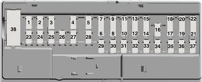
Arrangement of fuses under the instrument panel
| Number | Amperes [A] | Description |
|---|---|---|
| 1 | 10 A. | 2015-2017:
Lighting (surroundings, storage, courtesy, dome); 2017-2019: Not used. |
| 2 | 7.5A | Armchairs with memory;
Lumbar support; Electric mirror. |
| 3 | 20A | Unlocking the driver’s door. |
| 4 | 5A | Aftermarket electronic switch itrailer brake switch. |
| 5 | 20A | Ignition switch;
Push button ignition switch. |
| 6 | 10 A. | Heated seat relay coil. |
| 7 | 10 A. | Not used (spare). |
| 8 | 10 A. | Not used (spare). |
| 9 | 10 A. | Not used (spare). |
| 10 | 5A | Keyboard;Electrically lifted door module. |
| 11 | 5A | Not used. |
| 12 | 7.5A | Climate control;
Gear selector. |
| 13 | 7.5A | Steering column lock;
Group; Data link logic. |
| 14 | 10 A. | Not used. |
| 15 | 10 A. | Data link gateway module. |
| 16 | 15A | Childproof lock;
Liftgate release. |
| 17 | 5A | Not used (spare). |
| 18 | 5A | Ignition;
Start stop button. |
| 19 | 7.5A | Passenger airbag deactivation indicator;
Transmission range indicator. |
| 20 | 7.5A | Not used (spare). |
| 21 | 5A | Car humidity and temperature sensor;
Blind Spot Information System; Rear video camera; Adaptive cruise control. |
| 22 | 5A | Passenger classification sensor. |
| 23 | 10 A. | Delayed accessories (power inverter logic, sunroof logic). |
| 24 | 20A | Central lock. |
| 25 | 30A | Driver’s door (glass, mirror). |
| 26 | 30A | Front passenger’s door (glass, mirror). |
| 27 | 30A | Sunroof |
| 28 | 20A | Amplifier. |
| 29 | 30A | Driver’s side rear door (window). |
| 30 | 30A | Passenger’s rear door (window). |
| 31 | 15A | Not used (spare). |
| 32 | 10 A. | Global Positioning System (GPS);
Display; Voice control; Adaptive cruise control; Radio. |
| 33 | 20A | Radio. |
| 34 | 30A | Boot bus(fuse 19, 20, 21, 22, 35, 36, 37, circuit breaker). |
| 35 | 5A | Restriction control module. |
| 36 | 15A | Rearview mirror with automatic dimming function;
Heated seat; All-wheel drive. |
| 37 | 15A or 20A | Supply voltage stabilization module logic. |
| 38 | 30A | Not used (spare). |
Location of the fuse box
Fuses on the bottom of the fuse box
The scheme of the fuse box
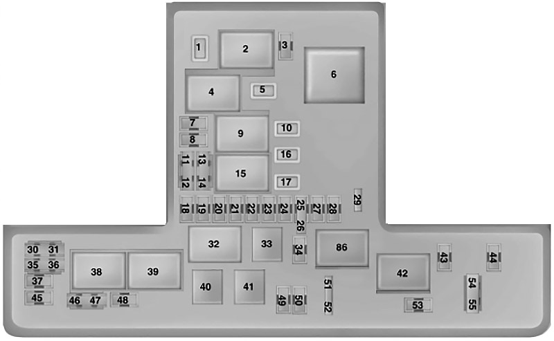
Arrangement of fuses in the engine compartment
| Number | Amperes [A] | Description |
|---|---|---|
| 1 | 25A | Wiper motor. |
| 2 | – | Starter relay. |
| 3 | 15A | Rear wiper;
Rain sensor |
| 4 | – | Blower motor relay. |
| 5 | 20A | Power point 3 – Back of the console. |
| 6 | – | Auxiliary heater relay No. 2. |
| 7 | 20A | Powertrain control module – vehicle power 1. |
| 8 | 20A | Powertrain control module – vehicle power 2. |
| 9 | – | Powertrain control module relay. |
| 10 | 20A | Power point 1 – driver’s front. |
| 11 | 15A | Powertrain control module – vehicle power 4. |
| 12 | 15A | Powertrain control module – vehicle power 3. |
| 13 | 10 A. | Not used (spare). |
| 14 | 10 A. | Not used (spare). |
| 15 | – | Start relay. |
| 16 | 20A | Power point 2 – console. |
| 17 | 20A | Power point 4 – trunk. |
| 18 | 10 A. | Not used (spare). |
| 19 | 10 A. | Electronic power steering in Run-Start mode. |
| 20 | 10 A. | Turn on / turn on the lighting. |
| 21 | 15A | Run transmission control. Switch gear oil pump on and off. |
| 22 | 10 A. | A / C clutch solenoid. |
| 23 | 15A | Run-Start;
Blind Spot Information System; Rear camera; Adaptive cruise control; Heads-up display; Voltage stabilization module. |
| 24 | 10 A. | Take-off 7. |
| 25 | 10 A. | System to prevent the wheels from locking during start-up. |
| 26 | 10 A. | Run-Start powertrain control module. |
| 27 | – | Not used. |
| 28 | 10 A. | Rear window washer pump. |
| 29 | – | Not used. |
| 30 | – | Not used. |
| 31 | – | Not used. |
| 32 | – | Electronic fan relay 1. |
| 33 | – | A / C clutch relay. |
| 34 | 15A | Electric steering column lock. |
| 35 | – | Not used. |
| 36 | – | Not used. |
| 37 | – | Not used. |
| 38 | – | Electronic fan relay 2 |
| 39 | – | Electric fan relay 2 and 3. |
| 40 | – | Headlight washer relay. |
| 41 | – | Horn relay. |
| 42 | – | Fuel pump relay. |
| 43 | 10 A. | Not used (spare). |
| 44 | 5A | Heated washer nozzle. |
| 45 | – | Not used. |
| 46 | 10 A. | Alternator sensor. |
| 47 | 10 A. | Brake on and off switch. |
| 48 | 20A | Horn |
| 49 | 25A | Diesel fuel heater. |
| 50 | 10 A. | Power transmission fan. |
| 51 | – | Not used. |
| 52 | – | Not used. |
| 53 | 10 A. | Electric seats. |
| 54 | 5A | Fuel heater. |
| 55 | 5A | Fuel heater. |
Fuse box diagram (bottom)
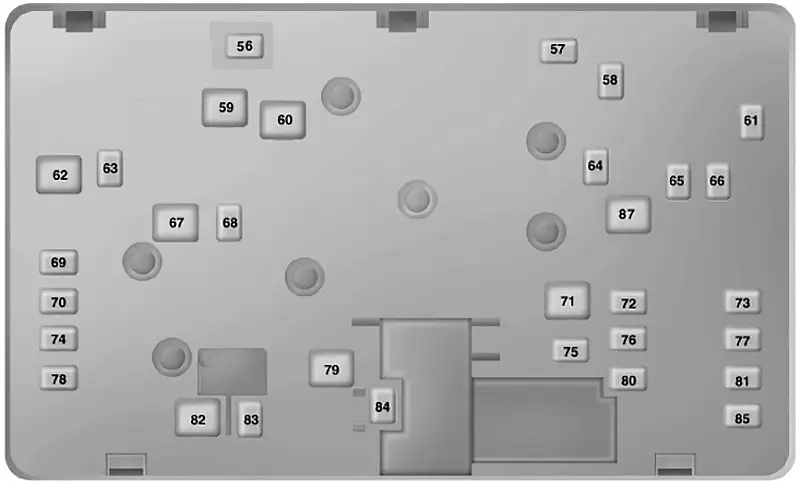
Fuse assignment in the engine compartment (bottom)
| Number | Amperes [A] | Description |
|---|---|---|
| 56 | 20A | Headlight washer. |
| 57 | 20A | Diesel evaporator. |
| 58 | 30A | Fuel pump supply. |
| 59 | 40A | Electronic fan 600W 3. |
| 60 | 40A | Electronic fan 600W 1;
Selective Catalytic Reducer System. |
| 61 | 40A | Left-hand windshield defrosting. |
| 62 | 50A | Body control module 1. |
| 63 | 25A | Electronic fan 600W 2. |
| 64 | 30A | Additional heater # 3. |
| 65 | 20A | Heated front seat. |
| 66 | 40A | Right-hand windshield defrosting. |
| 67 | 50A | Body control module 2. |
| 68 | 40A | Heated rear window. |
| 69 | 30A | Anti-lock braking system valves. |
| 70 | 30A | Passenger seat. |
| 71 | 60A | Additional heater # 2. |
| 72 | 30A | Electrically operated rear seats. |
| 73 | 20A | Heated rear seats. |
| 74 | 30A | Driver seat module. |
| 75 | 30A | Additional heater # 1. |
| 76 | 20A | Gear oil pump. |
| 77 | 30A | Seat module with air conditioning. |
| 78 | 40A | Trailer towing module. |
| 79 | 40A | Blower motor. |
| 80 | 40A | Electrically lifted door module. |
| 81 | 40A | 220V inverter. |
| 82 | 60A | Anti-lock brake system pump. |
| 83 | 25A | No.1 wiper motor. |
| 84 | 30A | Starter solenoid valve. |
| 85 | 20A | Fuel heater. |
| 86 | – | Not used. |
| 87 | 50A | Auxiliary blower motor. |