
Honda Insight (2010-2014) – fuse and relay box
Diagrams of fuse boxes and relays – Honda Insight
Applies to vehicles manufactured in the years:
2010, 2011, 2012, 2013, 2014.
The cigarette lighter (power outlet) fuse on the Honda Insight is fuse # 13 in the instrument panel fuse box.
Passenger compartment

- Fuse box
- Tire pressure monitoring system (TPMS) control unit
- Indicator control module
- Indicator control module
- Supplemental Restraint System (SRS) unit
- Electronic power steering (EPS) control unit
- Hatch release actuator relay
Distribution board fuse box diagram
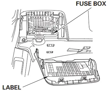
The internal fuse box is located behind the dashboard on the driver’s side. The label is stuck on the back of the cover. To see the inside label of the fuse box, remove the cover by pulling it towards you while holding the bottom center of the cover.


| Number | Amperes [A] | Description |
|---|---|---|
| 1 | 15 | Infotainment unit (with navigation), audio unit (without navigation), cargo area lighting, overhead lighting, data link connector (DLC), indicator control module, immobilizer keyless control unit, HandsFreeLink control unit, individual map lighting, integrated multiplex Unit control unit (MICU) (+ B BACK UP), motor control module (MCM) |
| 2 | 7.5 | Tire pressure monitoring system (TPMS) control unit |
| 3 | 20 | Window main switch |
| 4 | – | – |
| 5 | 10 | Backup light, Integrated Multiplex Control Unit (MICU) |
| 6 | 10 | Supplemental Restraint System (SRS) unit |
| 7 | 10 | Powertrain control module – PCM (VBSOL) |
| 8 | 7.5 | Passenger Sensing System (ODS) Module, Front Passenger Airbag Cut-Out Indicator, Supplemental Restraint System (SRS) Module |
| 9 | – | – |
| 10 | 7.5 | A / C Compressor Clutch Relay, Blower Motor Relay, A / C Unit, Fan Control Relay (A / C Diode), Option Connector, Power Mirror Switch, Radiator Fan Relay (A / C Diode), Rear Window Defogger Relay, Recirculation Control Motor |
| 11 | 7.5 | EPS control unit (IG1), VSA modulator control unit (IG1), Yaw acceleration sensor (with VSA), ABS modulator control unit (MTR) (without VSA) |
| 12 | 10 | DC-DC converter, Evaporative canister (EVAP) purge valve, powertrain control module – (idle switch), mass air flow (MAF) sensor, secondary heated oxygen sensor (HO2S) |
| 13 | 20 | Accessory power socket |
| 14 | 7.5 | Infotainment unit (with navigation), audio unit (without navigation), key lock solenoid, HandsFreeLink control unit, MICU (ACC), optional connector |
| 15 | 7.5 | Daytime running lights, Integrated Multiplex Control Unit (MICU) |
| 16 | 10 | REAR windshield wiper motor |
| 17 | 20 | Passenger’s front window motor, passenger’s front window switch |
| 18 | 20 | Right rear window motor, main window switch, right rear window switch light |
| 19 | 20 | Left rear power window motor, main power window switch, left rear power window switch |
| 20 | 15 | Fuel pump (PGM-FI main relay No.2 (2012-2014)), Immobilizer control unit – keyless entry, Powertrain control module – PCM (IG1) (2012-2014) |
| 21 | 15 | Washer motor, Integrated Multiplex Control Unit (MICU) |
| 22 | 7.5 | Electric Load Cell (ELD), Gauge Control Module, Integrated Multiplex – MICU Control Unit (IG1 Gauge), Engine Control Module (MCM), Shift Lock Solenoid, Tire Pressure Monitoring System (TPMS) control unit |
| 23 | 10 | Indicator / Hazard Relay, Integrated Multiplex Control Unit (MICU) |
| 24 | 10 | Brake pedal position switch, high mount brake light, left brake light, right brake light, horn relay, integrated multiplex control unit (MICU), powertrain control module (PCM) |
| 25 | – | – |
| 26 | 10 | Air Fuel Ratio (A / F) Sensor, Evaporative Emission Control (EVAP), Canister Vent Valve, Fuse: № 31 (7.5A) |
| 27 | thirty | Powered Door Lock, Integrated Multiplex Control Unit (MICU) |
| 28 | 20 | Headlamp (main), Integrated Multiplex Control Unit (MICU) |
| 29 | 10 | Parking light, Integrated Multiplex Control Unit (MICU) |
| 30 | thirty | Radiator fan motor (radiator fan relay), A / C condenser fan motor (fan control relay) (2012-2014) |
| 31 | 7.5 | A / C Condenser Fan Relay (A / C Diode B) |
| 32 | 10 | Right headlight (low beam) |
| 33 | 20 | Ignition Coil Relay, Fuses (Engine Compartment): №1 (15A), 2 (15A) |
| 34 | 10 | Left-hand headlight (low beam) |
| 35 | 15 | Passenger front door lock actuator, right rear door lock actuator |
| 36 | 15 | Driver door lock actuator, Left rear door lock actuator |
| 37 | thirty | Modulator-ABS control unit (without VSA), modulator-control unit VSA |
| 38 | 15 | Driver’s door lock actuator |
| 39 | 15 | Crankshaft Position (CKP) Sensor, Camshaft Position (CMP) Sensor, Electronic Throttle Control System (ETCS) Control Relay, Injectors, Powertrain Control Module – PCM (IGP), PGM-FI No.1 Main Relay, PGM Main Relay- FI No. 2 (Fuel pump) |
| 40 | – | – |
| 41 | – | – |
| 42 | 10 | Engine Control Module (MCM), MCM Relay # 1, MCM Relay # 2 |
| 43 | 7.5 | A / C compressor (A / C compressor clutch relay) |
| 44 | 7.5 | Starter relay, powertrain control module – PCM (STS) |
| 45 | 7.5 | Hatch release actuator relay, hatch release actuator |
| 46 | – | – |
| 47 | thirty | A / C Condenser Fan Motor (A / C Condenser Fan Relay), Radiator Fan Motor (Fan Control Relay) (2010-2011) |
| 48 | 10 | Left headlight (high beam) |
| 49 | 15 | Passenger front door lock actuator, right rear door lock actuator |
| 50 | 15 | Rear left door lock actuator |
| 51 | 10 | Right headlight (high beam) |
| 52 | 15 | Electronic Throttle Control System (ETCS), Powertrain Control Module – PCM (IG1ETCS) |
| 53 | 10 | Intelligent Power Supply Unit (IPU) Fan Module (Relay # 2 Motor Control Module (MCM)), Motor Inverter Module (MPI) (Motor Control Module (MCM) Relay # 2) |
| 54 | – | – |
| 55 | 10 | Left Power Mirror Defogger, Right Power Mirror Defogger |
| 56 | thirty | Front Wiper, Integrated Multiplex Control Unit (MICU) |
| 57 | thirty | Blower Motor (Blower Motor Relay) |
| 58 | thirty | Modulator-ABS control unit (without VSA), modulator-control unit VSA |
| 59 | thirty | Without Electric Mirror Defogger: Rear Window Defogger Relay (Lower Rear Window Defogger, Upper Rear Window Defogger, Noise Reduction Condenser) |
| 40 | With Electric Mirror Defogger: Rear Window Defogger Relay (Lower Rear Window Defogger, Upper Rear Defogger, Noise Reduction Condenser, Fuse: №55 (10A)) | |
| 60 | 50 | Ignition switch |
| thirty | Headlight washer | |
| R1 | Power window | |
| R2 | Blower motor | |
| R3 | Air Fuel Ratio (A / F) Sensor | |
| R4 | Lighting | |
| R5 | The ignition coil | |
| R6 | PGM-FI Main №1 | |
| R7 | Electronic Throttle Control System (ETCS) control | |
| R8 | Rear window defogger | |
| R9 | Unlock the driver’s door | |
| R10 | Starter cut | |
| R11 | – | |
Engine compartment
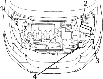
- Modulator-ABS control unit (without VSA), modulator-control unit VSA
- Powertrain control module (PCM)
- Relay box №1
- Relay box №2
Diagram of the fuse box in the engine compartment
The main fuses under the hood are located on the positive terminal of the battery. To open it, press the tabs as shown. These fuses are not serviceable; replace the battery terminal fuse box as an assembly.

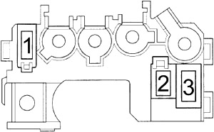
| Number | Amperes [A] | Description |
|---|---|---|
| 1 | 100 | DC-DC Converter, Light Relay, Window Relay, Driver’s Door Unlock Relay, Fuses: № 1, 2, 3, 9, 17, 18, 19, 25, 26, 27, 28, 29, 30, 32, 33, 34 , 37, 38, 39, 40, 41, 42, 43, 45, 46, 47, 52, 53, 57, 58, 59, 60 |
| 2 | 60 | Electronic Power Steering (EPS) |
| 3 | 20 | Fuses: 23, 24 |
Relay box 1

| Number | Amperes [A] | Protected ingredient |
|---|---|---|
| 1 | 15 | Ignition coils on the exhaust side |
| 2 | 15 | Upstream side ignition coils |
| R1 | Fan control | |
| R2 | PGM-FI Main №2 (Fuel Pump) | |
Relay box 2
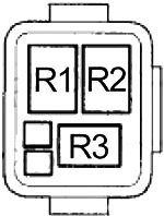
| Number | Relay |
|---|---|
| R1 | A / C condenser fan |
| R2 | Radiator fan |
| R3 | Air conditioning compressor clutch |