

Skoda Yeti (2013) – fuse and relay box
Diagrams of fuse and relay boxes – Skoda Yeti
Applies to vehicles manufactured in the years:
2013.
Fuse box in the dashboard
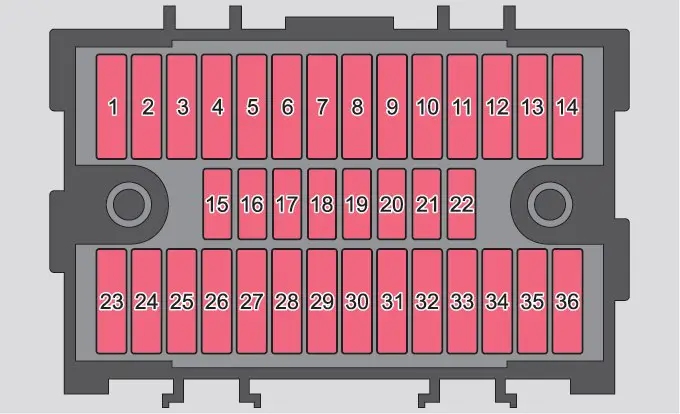
| Number | Description |
| 1 | Heating of gearbox ventilation (diesel engine);
Automatic gearbox control unit DQ200. |
| 2 | Towing device |
| 3 | Towing device |
| 4 | Instrument cluster;
Windshield wiper lever; Turn signal lever; Camera. |
| 5 | Heating blower;
Radiator fan; Air conditioning; Climatronic. |
| 6 | Rear window wiper |
| 7 | Telephone |
| 8 | Towing device |
| 9 | Vehicle voltage control unit – interior lighting, rear fog lamp |
| 10 | Rain sensor;
Light switch; Diagnostic socket. |
| 11 | Cornering light on the left-hand side |
| 12 | Cornering light to the right |
| 13 | Radio;
Changer for mobile navigation. |
| 14 | Towing device |
| 15 | Light switch |
| 16 | Haldex |
| 17 | Control unit for adjusting the headlamp beam and headlamp rotation |
| 18 | Diagnostic socket;
Motor controller; Brake sensor. |
| 19 | ABS controller;
ESP; Tire pressure control switch; Parking assist controller; OFF ROAD mode switch; START STOP button. |
| 20 | Airbag switch and control unit |
| 21 | WIV;
Parking lights; Dimmable mirrors; Pressure sensor; Telephone pre-installation; Air mass meter. |
| 22 | Instrument cluster;
Control unit for electromechanical power steering. |
| 23 | Central locking and bonnet cover |
| 24 | Rear electric window |
| 25 | Rear window heating;
Auxiliary heating and ventilation. |
| 26 | Power socket in luggage compartment |
| 27 | Electric sliding and tilting roof;
Electric sun visor. |
| 28 | Fuel pump;
Injection valves. |
| 29 | Front power window |
| 30 | Front and rear cigarette lighter |
| 31 | Headlight cleaning system |
| 32 | Front seat heating;
Seat heating regulator. |
| 33 | Heating;
Air conditioning; Climatronic; Parking heater remote control. |
| 34 | Alarm;
Spare horn. |
| 35 | Automatic transmission control unit DQ200 |
| 36 | DVD |
Fuse box in the engine compartment
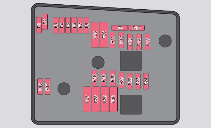
| Number | Description |
| F1 | Not assigned |
| F2 | Automatic gearbox control unit |
| F3 | Measuring circuit |
| F4 | ABS control unit |
| F5 | Automatic gearbox control unit |
| F6 | Instrument cluster;
Windshield wiper lever; Turn signal lever. |
| F7 | Power terminal 15;
Starter. |
| F8 | Radio |
| F9 | Telephone |
| F10 | Engine control unit |
| F11 | Auxiliary heating and ventilation control unit |
| F12 | Data bus control unit |
| F13 | Engine control unit |
| F14 | Ignition |
| F15 | Lambda probe;
Fuel pump relay; Glow plug arrangement. |
| F 16 | Vehicle voltage control unit;
Right headlight; Right rear light. |
| F17 | Horn |
| F18 | Amplifier for digital audio processor |
| F19 | Wipers |
| F20 | Fuel pressure control valve |
| F21 | Lambda probe |
| F22 | Clutch pedal switch;
Brake pedal switch. |
| F23 | Coolant pump;
Charge pressure control solenoid valve; Radiator diverting valve; Fuel high pressure pump. |
| F24 | Activated carbon filter;
Exhaust gas recirculation valve; Radiator fan. |
| F25 | ABS control unit |
| F26 | Vehicle voltage control unit;
Left headlight; Left tail light. |
| F27 | Glow plug system |
| F28 | Windshield heating |
| F29 | Interior power supply |
| F30 | Terminal Xa) |
| a) In order not to discharge the battery unnecessarily when starting the engine, the electrical components of this terminal are automatically disabled. | |