

Toyota Auris (2007-2013) – fuse box
Toyota Auris (2007-2013) – fuse box diagram
Year of production: 2007, 2008, 2009, 2010, 2011, 2012, 2013.
The cigarette lighter fuse (power socket) on the Toyota Auris is fuse 23 in the fuse box in the passenger compartment and fuse 39 in the engine compartment.
Engine compartment with electronics
location

Description
- Engine control unit
- Main fuse and relay box
- Glow plug relay
- Cooling fan control unit
- LHD: Headlight Wiper Relay
- Injector control unit (EDU)
- Relay box
- Gasoline: brake control unit
- Diesel: brake control unit
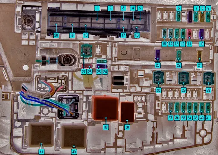
Fuse and relay box under the hood
It is located on the left side.
Type 1
Description
| F1 | 30А – Headlight washer |
| F2 | 45A – Cooling fan |
| F3 | 30А – ABS and VSC |
| F4 | 50А – ABS и VSC |
| F5 | 50A – Air conditioning |
| F6 | 10А – Automatic gearbox;
Air conditioning; Smart Entry System. |
| F7 | 10A – Instrumentation;
Electric control unit; VSC; Central lock; Drive of window lifters. |
| F8 | 15А – Audio system |
| F9 | 10A – Indoor lighting;
Luggage compartment lighting; Smart Entry System. |
| F10 | 20А – Steering lock system |
| F11 | 30A – Engine starting system;
Smart Entry system; Injection system. |
| F12 | 10A – Throttle control system |
| F13 | 10А – Direction indicators and hazard lights |
| F14 | 7,5А – Battery charging system |
| F15 | 7,5А – Electric devices control unit |
| F 16 | 50А – Headlights |
| F17 | 50A – Fuel injection system |
| F18 | 80А – Engine preheating system (for diesel engines) |
| F19 | 60A EPS – Electric power steering |
| F20 | 120А – Battery charging system |
| F21 | 15A – Fuel Injection System;
Smart Entry System. |
| F22 | 10А – Sound signal;
Horn |
| F23 | 20A – Fuel injection system |
| F24 | Reserve |
| F25 | Reserve |
| F26 | Reserve |
| F27 | 50A – Automatic gearbox |
| F28 | 30А – Air conditioner |
| F29 | 30А – Air conditioner |
| F30 | 30А – Air conditioner |
| F31 | 10А – Right headlight (low beam) |
| F32 | 10А – Left headlight (low beam) |
| F33 | 10А – Right headlight (high beam) |
| F34 | 10А – Left headlight (high beam) |
| F35 | 10A – Injection system |
| F36 | 10A – Injection system |
| F37 | 7.5A – Starting system;
Smart Entry System. |
| 38 | Cooling fan relay |
| 39 | Headlight switch relay |
| 40 | Automatic transmission relay |
| 41 | Headlight relay |
Type 2
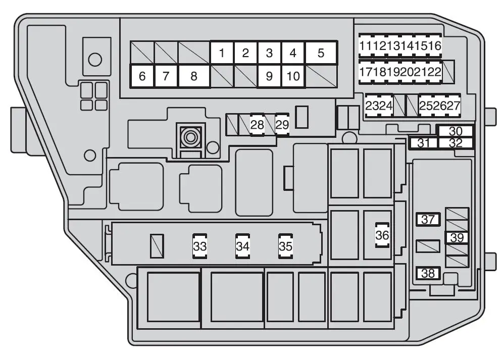
Description
| 1 | 30A – Electric cooling fan (s) |
| 2 | 40A – Electric cooling fan (s) |
| 3 | 30A – Anti-lock brake system, vehicle stability control system |
| 4 | 50A – Anti-lock brake system, vehicle stability control system |
| 5 | 50A – Air conditioning |
| 6 | 120А – Charging system, RDI FAN, CDS FAN, ABS NO. 1, ABS NO. 3, HTR, HTR SUB NO. 1, HTR SUB NO. 3, ACC, CIG, METER, IGN, ECU-IG NO. 2, HTR-IG, WIPER, WASHER, ECU-IG NO. 1, AM1, DOOR, STOP, FR DOOR, POWER, RR DOOR, RL DOOR, OBD, ACC-B, FR FOG, DEF, MIR HTR, TAIL, PANEL |
| 7 | 60A EPS – Electric power steering |
| 8 | 80А – Candles |
| 9 | 50А P / I – EFI MAIN, IG2 |
| 10 | 50А – Headlights |
| 11 | 10A – Emission Control System |
| 12 | 10A – Multiport fuel injection system;
Sequential multiport fuel injection system. |
| 13 | 10А – Right headlight (high beam) |
| 14 | 10А – Left headlight (high beam) |
| 15 | 10А – Right headlight (low beam) |
| 16 | 10А – Left headlight (low beam) |
| 17 | 10A – Electronic throttle control system |
| 18 | 10А – Direction indicators;Emergency flashers, |
| 19 | 7,5А – Charging system |
| 20 | 7.5A – Multiport fuel injection system;
Sequential Multiport Fuel Injection System; Starting system. |
| 21 | 30A – Starting system |
| 22 | 20А – Steering lock system |
| 23 | 7,5А – Starting system |
| 24 | 10A – Air conditioning system |
| 25 | 10A – Main body ECU;
Sensor and meters. Meter. |
| 26 | 15A – Audio system |
| 27 | 10A – Luggage compartment lighting;
Intelligent key system. |
| 28 | 30A – Audio system |
| 29 | 10А MAYDAY |
| 30 | 10A – Spare fuse |
| 31 | 30A – Spare fuse |
| 32 | 20A – Spare fuse |
| 33 | 20A – Multipoint fuel injection system;
Sequential multiport fuel injection system; EFI NO. 1, EFI NO. 2 |
| 34 | 10A – Horn |
| 35 | 15A – Multipoint fuel injection system;
Sequential multiport fuel injection system; Starting system; IGN; Meter. |
| 36 | 7,5А – Starter |
| 37 | 30A – PTC heater |
| 38 | 30A – PTC heater |
| 39 | 15А – Socket;
Lighter. |
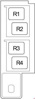
Additional relay box

Description
| R2 | Auxiliary heater (HTR SUB NO.1) |
| R3 | Auxiliary heater (HTR SUB NO.3) |
| R4 | Auxiliary heater (HTR SUB NO.2) |
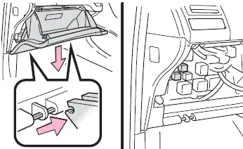
Passenger compartment
Layout diagram
General layout of the boxes in the cabin
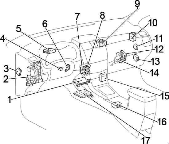
Description
- Air conditioner control unit
- Fuse box / body ECM
- LHD: Headlamp range control unit
- Steering lock control unit
- Power steering control unit
- Key transponder amplifier
- Relay box # 1
- Relay box no.2
- Distribution block
- Distribution block
- Wiper relay
- LHD : Gearbox control unit (multimode)
- Engine and gearbox control unit
- Start-Stop system control unit
- Multimedia interface control unit
- LHD: Shift Lever Lock Controller
- Airbag control unit
- RHD: Turn Signal Relay
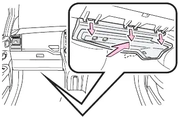
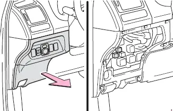
Fuse box
It is located in the passenger compartment under the panel on the left side.
Right hand drive
Left-hand drive

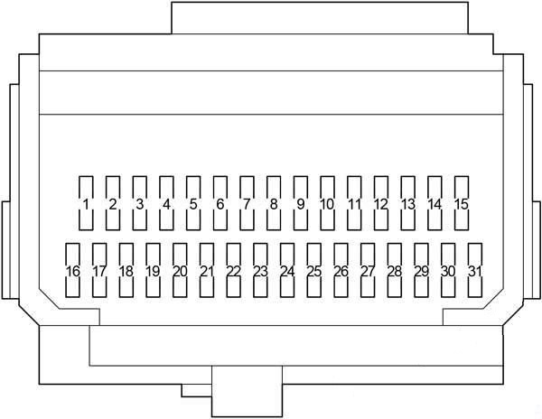
Description
| 1 | 7,5A – Starting system;
Multipoint fuel injection system; Sequential multiport fuel injection system; Fuses: “CIG”, “ACC”. |
| 2 | 15A – Front fog lamp |
| 3 | – |
| 4 | 25A – Fuses: “CIG”, “ACC” |
| 5 | 25А – Central locking |
| 6 | – |
| 7 | 10A – Stop lights;
Additional brake light; ABS; VSC; Body ECM; Multipoint fuel injection system; Sequential multiport fuel injection system; Gearbox control unit. |
| 8 | 7.5A – Diagnostic connector |
| 9 | 10A – Reversing lamps;Charging system;
Auto-dimming interior mirror; Monitor; Sunroof; Heated rear window; Air conditioning; Direction indicators; Emergency lights; Front passenger seat belt indicator; Start-stop system; Parking assistance system. |
| 10 | 10A – without start-stop system:
Automatic headlight range adjustment; Body ECM; Electric power steering; Cooling fan (s); Gear lever lock; Rain sensor; ABS; VSC; Audio system; Navigation; Sequential multiport fuel injection system; Headlight cleaning; Intelligent entry and start system. |
| 11 | 15A – Windshield washer |
| 12 | – |
| 13 | 25A – Doormat;
Rain sensor. |
| 14 | 10A – Air conditioning;
Heated rear window; Auxiliary heating. |
| 15 | 15A – Heated seats |
| 16 | 10A – Side light;
Number plate lighting; Rear fog light; Front fog lamp; Headlight range adjustment; Multipoint fuel injection system; Sequential multiport fuel injection system; Instrument panel lighting. |
| 17 | 7.5A – Light switch;
Instrument panel lighting; Glove box lighting; Steering wheel switches; Body control unit. |
| 18 | 10A – with start-stop system:
Automatic headlight range adjustment; Body ECM; Electric power steering; Cooling fan; Gear lever lock; Rain sensor; ABS; VSC; Audio system; Navigation; Multipoint fuel injection system; Sequential Multiport Fuel Injection System; Headlight cleaners; Intelligent entry and start system; Start-stop system. |
| 19 | 20A – Windshield lifters |
| 20 | 20A – Left rear window lifters |
| 21 | 20A – Right rear window lifters |
| 22 | 20A – Sunroof |
| 23 | 15А CIG – Cigarette lighter |
| 24 | 7.5 A – Electric mirrors;
Audio system; Navigation; Shift lock; Body ECM; Intelligent entry and start system; Start / Stop system. |
| 25 | |
| 26 | 10A – Heated mirrors;
Multipoint fuel injection system; Sequential multiport fuel injection system. |
| 27 | |
| 28 | |
| 29 | 7.5A – Rear fog light |
| thirty | 7.5 A – Steering system locks;
Airbags; Transmission control module; Multipoint fuel injection system; Sequential Multiport Fuel Injection System; Intelligent entry and start system; Start-Stop system. |
| 31 | 7.5A – Instrument cluster;
Start-stop system. |
Relays
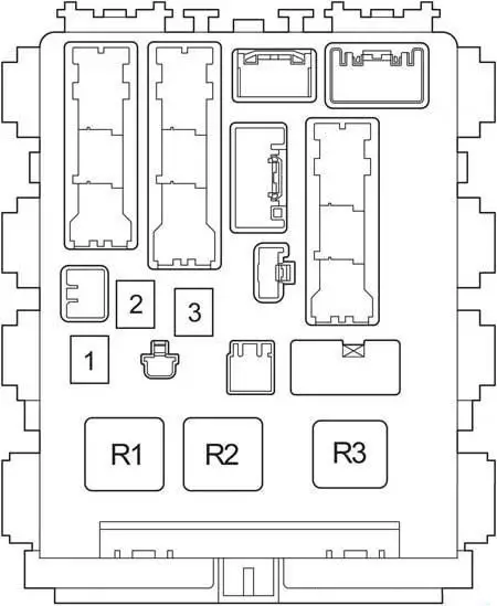
Description
| 1 | 30A body ECU;
Electricity of windows. |
| 2 | 30 / 40А Power supply for the indicator relay;
Rear window heating; Fuse: “MIR HTR”. |
| 3 | 30A Heated seats |
| R1 | “IG1” relay – ignition system |
| R2 | Heater relay |
| R3 | Relay – turn signal interrupter |
Relay box # 1

Description
| R1 | Starter (ST) |
| R2 | Rear fog light (RR FOG) |
| R3 | Auxiliary Relay (ACC) |
| R4 | Auxiliary Relay (ACC CUT) |
Relay box no.2
Description
| R1 | Front fog light (FR FOG) |
| R2 | Starter (ST CUT) |
| R3 | Panel (PANEL) |
| R4 | Reserve |