Volkswagen Tiguan (2006-2017) – fuse box
Volkswagen Tiguan – fuse box diagram
Year of production: 2006, 2007, 2008, 2009, 2010, 2011, 2012, 2013, 2014, 2015, 2016, 2017.
The cigarette lighter fuse (power socket) on the Volkswagen Tiguan is fuse 31 in the fuse box in the passenger compartment.
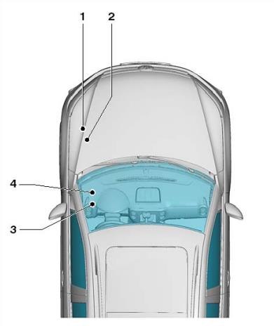
Locations
Description
- Main fuse box in the communication box
- Switching fuse box.
- Fuse box in passenger compartment.
- Relay box.
Engine compartment
It is located next to the battery.
Type 1
The scheme of the fuse box
Description
| 1 | |
| 2 | |
| 3 | 5A Onboard supply control unit |
| 4 | ABS 30A control unit;
ABS hydraulic unit. |
| 5 | |
| 6 | 5A Instrument cluster control unit;
Steering column control unit. |
| 7 | 40A Relay 2 power terminal 15 |
| 8 | 25A Control unit with display of radio navigation system;
Main unit; TV tuner; Digital satellite radio tuner; Multimedia system control unit; Voltage converter. |
| 9 | 5A Mobile phone control electronics control unit |
| 10 | 5 / 10A Power relay;
Engine control unit. |
| 11 | 20A Auxiliary heater control unit |
| 12 | 5A data bus diagnostic interface |
| 13 | 15 / 30A Engine control unit |
| 14 | 5A Fuel pressure regulator;
Fuel metering valve; Ignition coils. |
| 15 | 5/10 / 15A Electromagnetic clutch for a driving blower;
Lambda probe heater; Lambda probe 1 heater after the catalyst; Fuel system diagnostic pump; Fuel pump relay; Glow plug controller; Electric fuel pump relay 2. |
| 16 | 30A Onboard supply control unit |
| 17 | 15A Alarm siren relay |
| 18 | 30A Amplifier for digital audio system |
| 19 | 30A wiper motor control unit |
| 20 | 10A Fuel pressure regulator;
Coolant circulation pump. |
| 21 | 10 / 20A Lambda probe heater;
Fuel pump control unit. |
| 22 | 5A Clutch pedal position sensor |
| 23 | 10A Solenoid valve to limit the boost pressure;
Exhaust gas recirculation cooler switchover valve; Fuel pressure regulator; Air mass meter. |
| 24 | 10A Radiator fan controller;
Heating relay; Cooling system auxiliary pump relay; Power relay; Solenoid valve for boost pressure limitation; Solenoid valve 1 of the adsorber; Variable valve timing 1; Charge air recirculation valve; Intake manifold flap valve; Circulation pump 2 coolant; Coolant circulation pump; Fuel pump relay. |
| 25 | ABS 40A control unit |
| 26 | 30A Onboard supply control unit |
| 27 | Not used |
| 28 | 50A glow plug control unit |
| 29 | 50A Thermal fuse 1 for adjusting the position of the driver’s seat;
Fuses 54 – 57 in the passenger compartment. |
| 30 | 50A Relay for discharge contact X |
- A1 – Main ignition circuits relay (diesel)
- A2 – Engine control (EC) relay (diesel)
Type 2
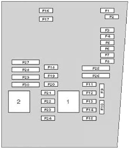
| 1 | 15A Block Mechatronik KP DSG |
| 2 | ABS 30A control unit |
| 3 | 15A horn relay |
| 4 | Reserve |
| 5 | 5A Onboard supply control unit |
| 6 | Reserve |
| 7 | 25A Voltage converter;
Control unit with display of the radio navigation system; Multimedia system control unit. |
| 8 | 40A Relay 2 power terminal 15 |
| 9 | Reserve |
| 10 | 5 / 10A Lambda probe heater;
Drive blower electromagnetic clutch; Fuel system diagnostic pump; Glow plug controller. |
| 11 | 5A Instrument cluster control unit;
Steering column control unit. |
| 12 | 5A Mobile phone control electronics control unit |
| 13 | 5 / 10A Engine control unit |
| 14 | 15 / 30A Engine control unit |
| 15 | 5A data bus diagnostic interface |
| 16 | 10A Solenoid valve to limit boost pressure;
Recirculation cooler diverter valve; Air flow meter; Fuel pressure regulator. |
| 17 | 10 / 15A Fuel pressure regulating valve;
Coolant circulation pump. |
| 18 | 10A Lambda probe heater;
20A Fuel pump control unit. |
| 19 | 30A Amplifier for digital audio system |
| 20 | 5A Clutch pedal position sensor |
| 21 | 30A Additional heater control unit |
| 22 | 30A wiper motor control unit |
| 23 | 10A High heating power relay;
Low heating power relay; Fuel pump relay; Coolant circulation pump 2; Radiator fan control unit; Electric fuel pump relay 2; Solenoid valve to limit the boost pressure; Charge air recirculation valve; Canister 1 solenoid valve; Valve 1 variable timing systems; Intake manifold flap valve; Motronic 2 power relay; Brake light switch. |
| 24 | 20A Ignition coils;
15A Fuel metering valve. |
| 25 | 30A Onboard supply control unit |
| 26 | 30A Onboard supply control unit |
| 27 | 50A Relay for discharge contact X |
| 28 | 50A glow plug control unit |
| 29 | 50A Thermal fuse 1 for adjusting the position of the driver’s seat;
Fuses 54 – 57 in the passenger compartment. |
| 30 | 40A ABS control unit (pump) |
Main fuses
Description
- 200A – Generator
- 80A – Power steering control unit
- 50A – Fuse 40 in the fuse box
- 50A – Radiator fan control unit
- 80A – Fuse box
- 70A – Radiator fan controller, high power heating relay
- Reserve
- 40A – Low-power heating relay
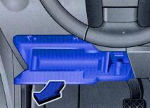
Passenger compartment
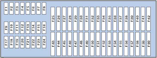
Fuse box
Description
| 1 | Not used |
| 2 | Not used |
| 3 | Not used |
| 4 | Not used |
| 5 | Not used |
| 6 | Not used |
| 7 | Not used |
| 8 | Not used |
| 9 | 5A Airbag control unit;
Indicator light off; Front passenger airbags. |
| 10 | 10A All-wheel drive controller |
| 11 | 5A Autopilot or parking assist control unit |
| 12 | 10A Left discharge headlight control unit |
| 13 | 5A High pressure sensor;
Electrochromic interior rear-view mirror; Reverse light switch; Washer nozzle heating resistor; AUTO HOLD button; AUTO HOLD indicator light; Chair occupancy recognition controller; Driver assistance systems front camera; Engine oil level and temperature sensor; ASR and ESP off key; Driving program key. |
| 14 | 10A Power steering control unit;
Vehicle position tracking control unit; Starter relay; Electronic damping control unit; Trailer detection control unit; Tiptronic switch; Data bus diagnostic interface; Control unit in the instrument cluster; Heating control unit; Light switch; Engine control unit; ABS control unit. |
| 15 | 10A Relay for auxiliary heater operation;
Voltage converter; Adaptive lighting control unit and headlight range adjustment; Air mass meter; Diagnostic connector; Electromechanical parking brake control unit; Dimmer for switches and instrument cluster illumination; Heating resistor of the crankcase ventilation system; Engine headlight corrector control; Right headlight corrector actuator. |
| 16 | 10A Right discharge headlight control unit |
| 17 | 5A Instrument cluster control unit |
| 18 | 5A Control unit for the control electronics of a mobile telephone;
Multimedia system control unit; Magnetic field sensor for compass. |
| 19 | 7.5A Steering column control unit |
| 20 | 5 / 7.5A Tire pressure monitor control unit;
Radio signal receiver for additional coolant heater; Heated rear window relay; Two-tone sound signal relay; ABS control unit; Tiptronic switch; Automatic gearbox control unit; Air conditioning control unit; Climatronic control unit; Heater control unit. |
| 21 | 7,5 / 15A On-board power controller;
Front passenger door control unit; Rear right door control unit. |
| 22 | 5A Onboard supply control unit;
Alarm siren; Internal sensor. |
| 23 | 10A Rain and light sensor;
Light switch; Vehicle position tracking control unit; Entry and start authorization control unit; Reversing camera control unit; Magnetic field sensor for compass; Electromechanical parking brake button; Diagnostic connector. |
| 24 | 10A Driver’s door control;
Rear left door control unit. |
| 25 | 5 / 20A Multifunction switch;
Automatic gearbox control unit; Mechatronic unit DSG. |
| 26 | Not used |
| 27 | Not used |
| 28 | 40A Relay for auxiliary heater operation;
Heater control unit; Air conditioning control unit. |
| 29 | 15A Rear window wiper motor |
| 30 | Not used |
| 31 | 20A Cigarette lighter and 12V socket |
| 32 | Not used |
| 33 | Not used |
| 34 | Not used |
| 35 | Not used |
| 36 | Not used |
| 37 | Not used |
| 38 | 10A Electronic steering column lock control unit |
| 39 | 20A Relay for headlight cleaning system |
| 39 | 15A Trailer recognition control unit and preparation for towing hitch |
| 40 | 15A Trailer recognition control unit |
| 41 | 15A Trailer recognition control unit |
| 42 | 20A Trailer recognition control unit |
| 43 | 25A Control for sliding sunroof |
| 44 | 25A Electromechanical parking brake control unit |
| 45 | 25A Supply fan relay;
Heated rear window relay. |
| 46 | 30A Driver’s door control;
Rear left door control unit. |
| 47 | 30A Front passenger door control unit;
Rear right door control unit. |
| 48 | 20A Fuel pump relay |
| 49 | 20A Onboard supply control unit |
| 50 | 25A Electromechanical parking brake control unit |
| 51 | 40A Supply fan control unit |
| 52 | 20 / 30A Front seat heating control unit |
| 53 | 20 / 30A Relay for headlight cleaning system |
| 54 | 30A Inverter with socket, 12V – 230V |
| 55 | 15A Driver’s seat lumbar support adjustment switch |
| 56 | 15A Electronic damping control system control unit |
| 57 | 25A sunroof control unit |
| 58 | 1A Traction hook warning lamp (locked) |
| 59 | Control unit with display for the radio navigation system |
| 60 | Not used |
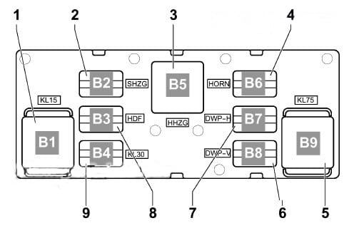
Relay box
Description
- Power relay terminal 15 2, -J681-, (460) Socket B1
- Heated exterior mirror relay -J99- (449) Socket B2
- Heated rear window relay -J9- (53) Socket B5
- Two tone horn relay -J4- (449) Socket B6
- X Contact relief relay -J59- (460) Slot B9
- Double washer pump relay 2 -J730- (404) Socket B8
- Relay 1 for double washer pump -J729- (404) Socket B7
- Book slot B3
- Power relay 2 terminal 30 -J689- (449) Socket B4
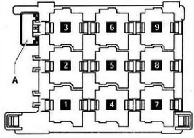
Description
- Auxiliary heater relay
- Starter relay
- –
- Heater fan relay
- Burglar alarm relay / Headlight washer pump relay
- Fuel pump relay (FP)
- Engine coolant heater relay 1
- Engine coolant pump relay – some models, fuel pump (FP) relay – some models, auxiliary heater fuel pump – some models
- Engine coolant heater relay 2.

