

Ford Contour (1995-2000) – fuse and relay box
Fuse and relay box diagrams – Ford Contour
Applies to vehicles manufactured in the years:
1995, 1996, 1997, 1998, 1999, 2000.
Distribution board fuse box diagram
The instrument panel fuse panel is located under the left instrument panel. To open it, reach under the instrument panel and press the release button on the right side of the fuse panel.
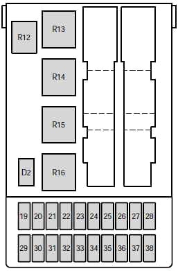
| Number | Amperes [A] | Description |
|---|---|---|
| 19 | 7.5 | 1995-1997: Heated rear view mirrors |
| 20 | 10 | Wiper motors (switch) |
| 21 | 40 | Electric windows |
| 22 | 7.5 | 1995-1997: ABS module |
| 23 | 15 | Spare lamps |
| 24 | 15 | Brake lights |
| 25 | 20 | Locks |
| 26 | 7.5 | Main light |
| 27 | 15 | Lighter |
| 28 | thirty | Electric seats |
| 29 | thirty | Rear window defrosting |
| 30 | 7.5 | Engine management system |
| 31 | 7.5 | Instrument panel illumination |
| 32 | 7.5 | Radio |
| 33 | 7.5 | Parking lights – driver’s side |
| 34 | 7.5 | Interior lighting / electric mirror adjustment / clock |
| 35 | 7.5 | Parking lights – passenger side |
| 36 | 10 | 1995-1998: Airbag |
| 37 | thirty | Heater blower motor |
| 38 | – | – |
| R12 | Indoor lighting | |
| R13 | Rear window defrosting | |
| R14 | Heater blower motor | |
| R15 | Wiper motor | |
| R16 | Ignition | |
| D2 | Reverse voltage protection | |
To check or replace a fuse or relay, remove the engine compartment fuse box cover by releasing the latch and lifting it.
Scheme 1995-1998
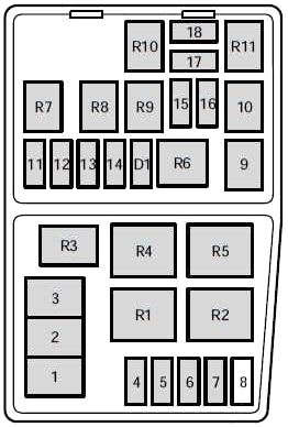
| Number | Amperes [A] | Description |
|---|---|---|
| 1 | 80 | Main power supply for the vehicle’s electrical system |
| 2 | 60 | Engine cooling fan |
| 3 | 60 | ABS brake system, heater blower |
| 4 | 20 | Ignition, EEC module, daytime running lights |
| 5 | 15 | Fog light |
| 6 | – | – |
| 7 | 20 | 1998: ABS system |
| 7 | thirty | 1995-1997: ABS system |
| 8 | thirty | 1995-1998: Air pump |
| 9 | 20 | Electronic engine control (EEC) |
| 10 | 20 | Ignition switch |
| 11 | 3 | EEC ignition module (memory) |
| 12 | 15 | Warning system for horn and hazard lights |
| 13 | 20 | 1998: HEGO sensor |
| 13 | 15 | 1995-1998: HEGO sensor |
| 14 | 15 | Electrically operated fuel pump |
| 15 | 10 | Dipped beam headlamp – (passenger side) |
| 16 | 10 | Dipped beam headlamp – (driver’s side) |
| 17 | 10 | High Beam Headlamp – (Passenger Side) |
| 18 | 10 | High Beam Headlamp – (Driver’s Side) |
| R1 | Day lights | |
| R2 | Radiator fan relay (high speed) | |
| R3 | Air conditioning | |
| R4 | Air conditioning clutch | |
| R5 | Radiator fan relay (low speed) | |
| R6 | Starter solenoid | |
| R7 | Horn | |
| R8 | Fuel pump | |
| R9 | Dipped beam headlamps | |
| R10 | High beam headlamps | |
| R11 | PCM module | |
| D1 | Reverse voltage protection | |
Scheme 1999-2000
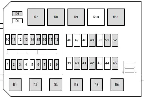
| Number | Amperes [A] | Description |
|---|---|---|
| 1 | – | – |
| 2 | 7.5 | Alternator |
| 3 | 20 | Fog lights |
| 4 | – | – |
| 5 | – | – |
| 6 | 3 | EEC ignition module (memory) |
| 7 | 20 | Warning system for horn and hazard lights |
| 8 | – | – |
| 9 | 15 | Fuel pump |
| 10 | – | – |
| 11 | 20 | Ignition, electronic engine control |
| 12 | – | – |
| 13 | 20 | HEGO sensor |
| 14 | 7.5 | ABS module |
| 15 | 7.5 | Dipped beam headlamp (passenger side) |
| 16 | 7.5 | Dipped beam headlamp (driver’s side) |
| 17 | 7.5 | High beam headlamp (passenger side) |
| 18 | 7.5 | High-beam headlamp (driver’s side) |
| 39 | – | – |
| 40 | 20 | Ignition, light switch, central junction box |
| 41 | 20 | EEC relay |
| 42 | 40 | Central junction box (fuse 37 to blower relay) |
| 43 | – | – |
| 44 | – | – |
| 45 | 60 | Ignition |
| 46 | – | – |
| 47 | – | – |
| 48 | – | – |
| 49 | 60 | engine cooling |
| 50 | – | – |
| 51 | 60 | ABS |
| 52 | 60 | Central junction box (central timer module, rear window defroster relay, fuses 24, 25, 27, 28, 34) |
| R1 | Fuel pump | |
| R2 | EEC module | |
| R3 | Air conditioning | |
| R4 | Dipped beam | |
| R5 | Traffic lights | |
| R6 | Horn | |
| R7 | Starter solenoid | |
| R8 | Engine cooling fan (high speed) | |
| R9 | Engine cooling fan | |
| R10 | – | |
| R11 | Day lights | |
| D1 | Reverse voltage protection | |
| D2 | – | |
Relays outside fuse boxes
| Number | Description | Location |
|---|---|---|
| R18 | One touch switch (driver’s window) | Driver’s door |
| R20 | – | – |
| R21 | – | – |
| R22 | Fog lights | Wire cover on the switchboard |
| R23 | Direction indicators | Steering column |
| R24 | Panic alarm – driver side | Door lock module bracket |
| R25 | Panic alarm – right side | Door lock module bracket |
| R26 | – | – |
| R32 | Heater control Hego | Near the PCM |