

Toyota RAV4 XA30 and CA30 (2006-2012) – fuse box
Toyota RAV4 XA30 and CA30 – fuse box diagram
Year of production: 2006, 2007, 2008, 2009, 2010, 2011, 2012.
The Cigarette Lighter (Power Outlet) fuses on the Toyota RAV4 are fuses 23 (cigarette lighter), 24 (power outlets), 27 (power outlets), 12 in the instrument panel fuse box and fuse 18 (115V power outlet) in the engine compartment fuse box No. 1.
Engine compartment
location

Description
- Fuse and relay box # 1
- 2AD-FHV, 2AD-FTV: Injector Control Unit (EDU) (from December 2008)
- 2AD-FHV: Injector Control Unit (EDU) (up to December 2008)
- 2AD-FTV: Injector Control Unit (EDU) (up to December 2008)
- Valvematic
- ABS control unit
- Fuse and relay box # 2
- Engine control unit
- Transmission control unit
- Cooling fan control unit or left cooling fan control unit
- Glow plug relay
- Right cooling fan control unit
- Headlight wiper relay
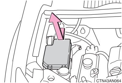
Fuse and relay box 1
On the right under the hood.
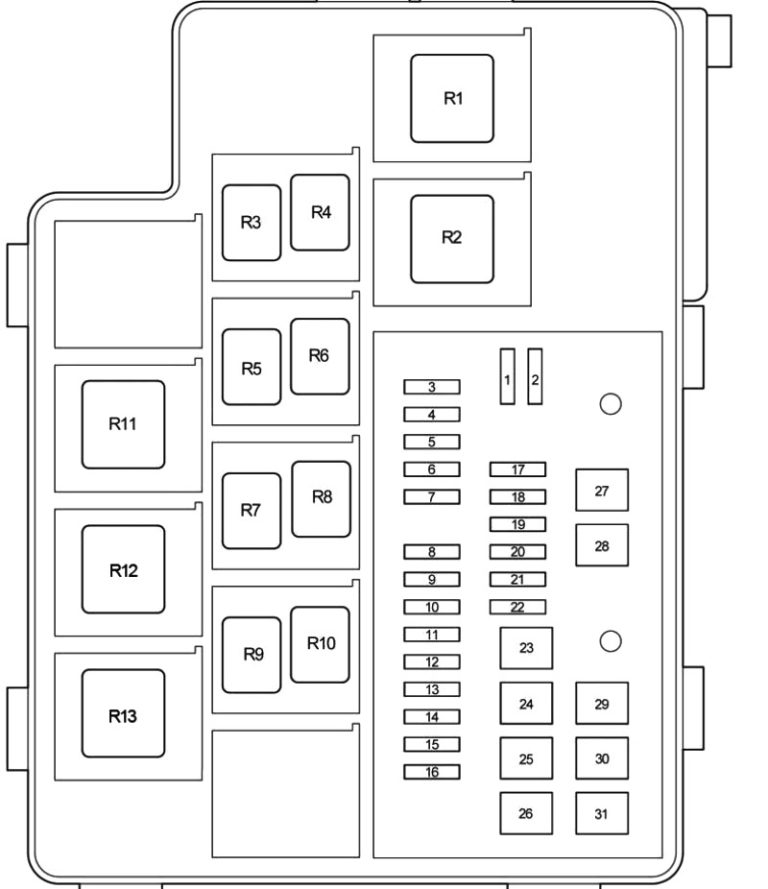
Description
| 1 | Not used |
| 2 | Not used |
| 3 | Not used |
| 4 | 7.5A – Air conditioning;Electric windows. |
| 5 | 7,5A – Charging system |
| 7.5A – audio system (JBL) | |
| 6 | 20A – Steering Lock System (with Keyless Entry and Start System) |
| 7 | Not used |
| 8 | DCC |
| 9 | 20A – Audio system |
| 10 | 10A – Wireless remote control system;
Power steering; Body electronics; Clock; Instrument cluster; Keyless system; Opening and starting; Central lock; Audio system; Navigation system; Instrumentation. |
| 11 | 10A – Ignition switch illumination;
Engine start button illumination (with keyless entry and start system); “ENGINE START STOP” switch illumination (with keyless entry and start system); Interior lighting; Cosmetic mirror lighting; Luggage compartment lighting; Personal lighting; Lighting of the lower part of the cabin. |
| 12 | – |
| 13 | 10A – Left main beam light |
| 14 | 10A – Right main beam light |
| 15 | 10A – Left dipped beam |
| 16 | 10A – Right dipped beam |
| 17 | – |
| 18 | 15A – Socket (115V) |
| 19 | 30A – Trailer connector |
| 20 | 25A – Autonomous passenger compartment heater |
| 21 | Not used |
| 22 | 20A – Heated zone of the remaining windshield wiper blades |
| 23 | 50A – Air conditioning |
| 24 | 50A – Auxiliary heater |
| 25 | 50A 840W: Auxiliary heater |
| 30A 300W: Auxiliary heater | |
| 26 | 50A 840W: Auxiliary heater |
| 30A 300W: Auxiliary heater | |
| 27 | 50A – Fuses: 13, 14, 15, 16. |
| 28 | Not used |
| 29 | 30A – Cooling fan |
| 50A – 2GR-FE with hitch option: Cooling fan | |
| 30 | 30A – Cooling fan |
| 50A – 2GR-FE with hitch option: Cooling fan | |
| 31 | 30A – Headlight cleaning |
| R1 | Light switch, high beam |
| R2 | Headlamps, low beam |
| R3 | Daytime running lights (No.4) |
| R4 | Daytime running lights (No.3) |
| R5 | Except for 2GR-FE: Cooling fan (No.3) |
| R6 | Except for 2GR-FE: Cooling fan (No.2) |
| R7 | Except for 2GR-FE: Cooling fan (No.1) |
| R8 | Not used |
| R9 | Heated zone of the remaining windscreen wiper blades |
| R10 | Daytime running lights (No.2) |
| R11 | Except for 2GR-FE: Auxiliary heater |
| R12 | Except for 2GR-FE: Auxiliary heater |
| 2GR-FE: Cooling Fan (No.2) | |
| R13 | 2GR-FE: Cooling Fan (No.1) |
| Except for 2GR-FE: Auxiliary heater |
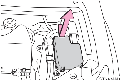
Fuse and relay box 2
On the left side of the engine compartment.
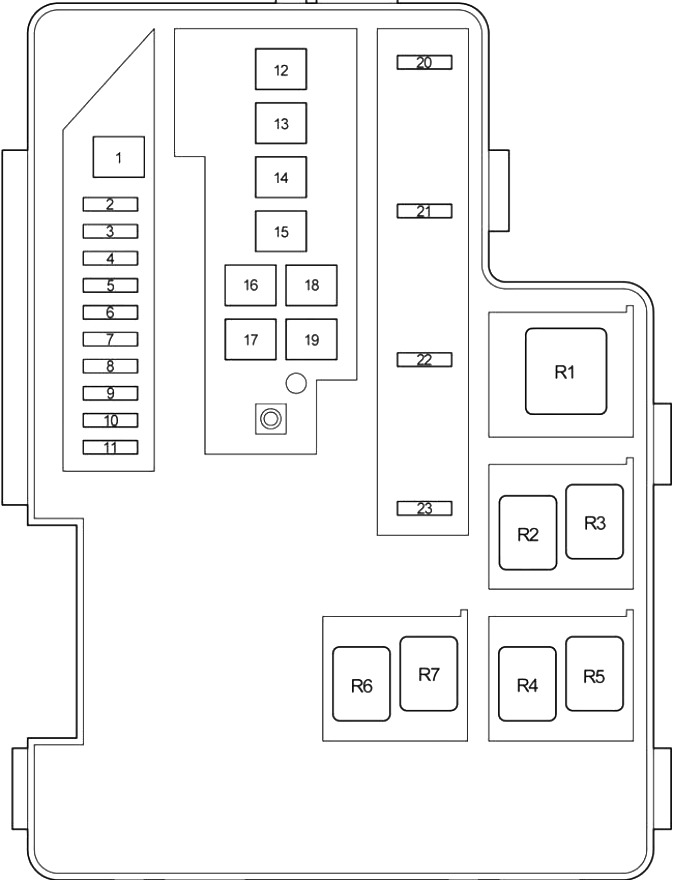
Description
| 1 | 30A – 3ZR-FAE: Valvematic |
| 2 | 30A – Audio system (JBL) |
| 3 | 30A – Starting system |
| 4 | 15A – Engine starting system;
Multipoint fuel injection system; Sequential multiport fuel injection system. |
| 5 | 10A – Alarm |
| 6 | 10A – Multipoint fuel injection system;
Sequential multiport fuel injection system. |
| 7 | 7.5A – Starting system |
| 8 | – |
| 9 | 10A Multiport fuel injection system;
Sequential multiport fuel injection system. |
| 10 | 10A – Multipoint fuel injection system;
Sequential multiport fuel injection system. |
| 11 | 7.5A – A / T; from December 2008:
Multiport fuel injection system; Sequential multiport fuel injection system |
| 7,5A – Starting system;
Multipoint fuel injection system; Sequential multiport fuel injection system. |
|
| 12 | 80A – Heating system |
| 13 | 60A – Power steering |
| 14 | 80A – Fuses: 27, 4, 11, 10, 9. |
| 15 | 120A ALT – Gasoline engines, vehicles without coupling options:
Fuses: “ABS 1”, “ABS 2”, “RDI”, “CDS”, “HTR”, “HOWING” |
| 140A ALT – Diesel engines, vehicles with hitch option:
Fuses: “ABS 1”, “ABS 2”, “RDI”, “CDS”, “HTR”, “HOWING” |
|
| 16 | 50A – Fuses: “EFl MAIN”, “HORN”, “A / F”, “EDU” |
| 17 | Not used |
| 18 | 30A – Anti-lock braking system (ABS);
Traction control; Vehicle Stability Assist; Hill descent assistant; Hill descent assistant. |
| 19 | 50A – ABS, anti-lock braking system;
Traction control system; Vehicle Stability Assist; Hill descent assistant. |
| 20 | 20A – Multipoint fuel injection system;
Sequential multiport fuel injection system; Fuses: “EFI NO. 1”, “EFI NO. 2”, “EFI NO. 3”. |
| 21 | 10A – Horn |
| 22 | 25A – Multipoint fuel injection system;
Sequential multiport fuel injection system. |
| 23 | 20A – Gasoline:
Multiport fuel injection system / sequential multiport fuel injection system |
| 20A – Diesel:
Multiport fuel injection system / sequential multiport fuel injection system |
|
| 15A – 3ZR-FAE:
Multiport fuel injection system / sequential multiport fuel injection system |
|
| R1 | Vehicle stability system |
| R2 | Not used |
| R3 | Vehicle stability system |
| R4 | Ignition (IG2) |
| R5 | Anti-lock braking system |
| R6 | Air conditioning compressor clutch |
| R7 | Fuel pump |
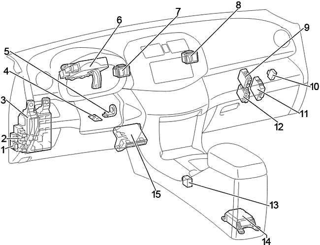
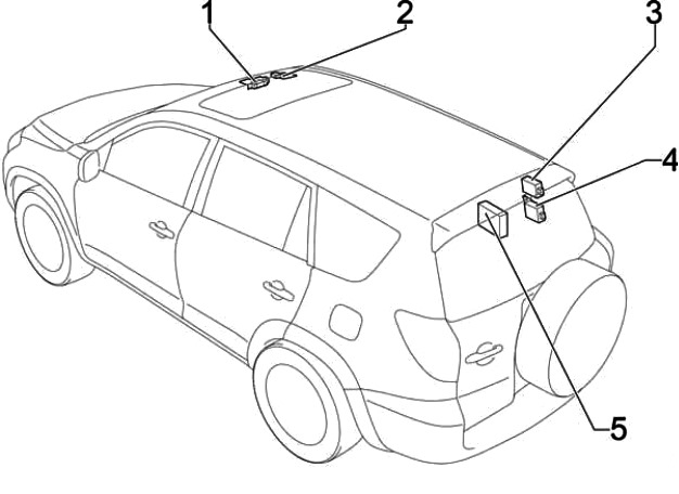
Passenger compartment
location
Left Hand Drive (LHD)
Right hand drive (RHD)
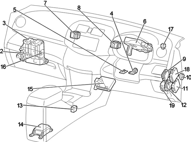
Description
- LHD: Relay box # 2
- Relay box # 1
- Fuse box / body ECM
- Key transponder amplifier
- Steering lock control unit
- Power steering control unit
- Distribution block
- Distribution block
- Tire pressure monitoring system control unit
- Brake light relay
- All-wheel drive control unit
- Automatic wiper relay
- Gear lever lock control unit
- Airbag central control unit
- Air conditioner amplifier
- RHD: Starter relay (ST) (Gasoline, Before Dec 2008: Diesel with Keyless Entry and
Starting ) Jumper (Before Dec 2008: Diesel engines without Keyless Entry and Starting) - RHD: Turn Signal Relay (Warning Lamps)
- RHD: Anti-theft control unit
- RHD: Double interlock control unit
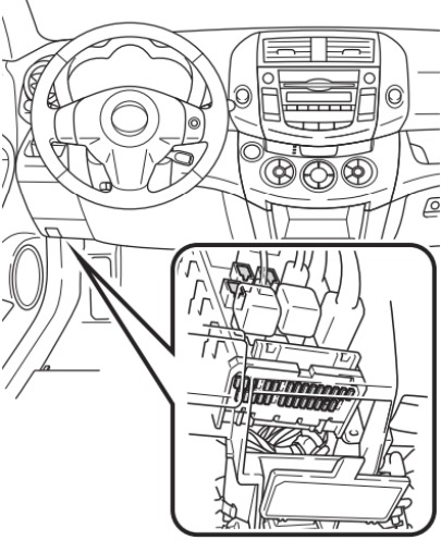
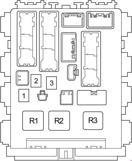
Fuse box
In the diagram, it is marked with the number 3 .
It is located under the dashboard on the left side of the steering wheel.
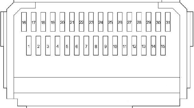
Description
| 1 | Not used |
| 2 | 15A – Heated seats |
| 3 | 25A – Screen wiper |
| 4 | 15A – Rear wiper |
| 5 | 15A – Windshield washer;
Rear window washer. |
| 6 | 10A – Cooling fan;
ABS; Anti-skid system; Stability control system; Uphill traction assist system; Hill assist system; AWD system with electronic torque distribution; Air conditioning system; Body electronics; Sunroof; Auto-dimming interior mirror; Brake lights; Position lights; Heated wiper blades; Power steering; Disengaging the clutch; Headlight cleaner; Heater; Clock. |
| 7 | 10A – Air conditioning;
Heated rear window. |
| 8 | 7,5A – Z Diagnostic connector |
| 9 | 10A – Stop lights;
Additional brake light; Gear lever lock; Multipoint fuel injection system; Sequential multiport fuel injection system; ABS; Anti-skid system; Stability control system; Uphill traction assistance; Slope Traction Control. |
| 10 | Not used |
| 11 | 25A – Body electronics;
Central lock. |
| 12 | 25A – Fuses: “ACC”, “CIG” |
| 13 | 7.5A 4WD – All-wheel drive with electronic torque distribution |
| 14 | 15A – Front fog lamp |
| 15 | 7.5A – Starting system |
| 16 | 10A – Side light;
License plate lighting; Front fog lamp; Rear fog light. |
| 17 | 7,5A – Audio system;
Dashboard illumination; Clock. |
| 18 | 10A – Reversing lamps, charging system |
| 19 | 20A – Windows (entrance door) |
| 20 | 20A – Window regulator (left rear door) |
| 21 | 20A – Window regulator (rear right door) |
| 22 | 25A – Sunroof |
| 23 | 15A – Cigarette lighter |
| 24 | 7,5A – Audio system;
Electric sockets; Electric mirrors; Gear lever lock; Body electronics; Clock. |
| 25 | Not used |
| 26 | 10A – Heated mirrors |
| 27 | 15A – Power socket |
| 28 | Not used |
| 29 | 10A – Rear fog light |
| 30 | 7.5A – Airbags;
Multipoint fuel injection system; Sequential multiport fuel injection system; Brake lights; Position lights; Starter layout. |
| 31 | 7.5A – Instrument cluster |
Relays
Circuit breakers
- 30A – Electric windows
- 30A DEF – Heated rear window, fuse: “MIR HTR”
- 30A P / SEAT – Electric seat
Relay
- R1 – Ignition (IG1)
- R2 – Heater (mechanical air conditioner) / Jumper (automatic air conditioner)
- R3 – LHD: Direction indicators (warning lights)
Relay box
It is located next to the fuse box.
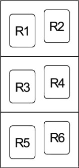
Description
| R1 | Starter (ST CUT) |
| R2 | LHD: Starter (ST) (petrol, before Dec 2008:Diesel with Keyless Entry and Starting) |
| LHD: Short starter (before Dec. 2008: diesel engines without keyless entry and starting) | |
| R3 | Front fog lamp |
| R4 | Rear fog light |
| Socket (115V) | |
| R5 | Auxiliary relay |
| R6 | Power socket |
Additional items
Description
- Distribution block
- Sunroof control unit
- Antenna and receiver for tire pressure monitoring system
- Central locking receiver
- Sound amplifier