

Audi A8 D2 (1994-2002) – fuse box
Audi A8 D2 (1994-2002) – fuse box diagram
Year of production: 1994, 1995, 1996, 1997, 1998, 1999, 2000, 2001, 2002.
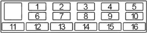
The cigarette lighter fuse (power socket) on the Audi A8 D2 (1994-2002) is fuse 13 in the fuse box in the passenger compartment.
Passenger compartment fuse box
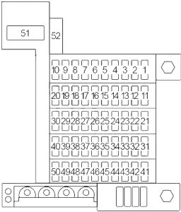
| Number |
Amperes [A] |
Description |
| GRAY | ||
| 1 | 5 | Lamp control module,left parking light,
left front clearance lamp, the instrument cluster composite processor |
| 2 | 5 | Lamp control module;
Right parking light; Right front marker lamp; Tail lights; Number plate lighting; Indicator bank processor. |
| 3 | 15 | ’97 -’03:
Right headlight (low beam); Lamp control module. |
| 10 | Right headlight (low beam);
Lamp control module. |
|
| 4 | 15 | ’97 -’03:
Left headlight (low beam); Headlight aiming system; Lamp control module. |
| 10 | Left headlight (low beam);
Headlight aiming system; Lamp control module. |
|
| 5 | 10 | Left headlight (high beam);
front / rear control module the fog lamps. |
| 6 | 10 | Right headlight (high beam);
High beam indicator light. |
| 7 | 15 | Emergency warning light switch |
| 8 | 15 | Horn |
| 9 | 10 | 00-03:
Data link connector. |
| 5 | ’98 -’99:
Data link connector; Selector lever light relay. |
|
| 5 | -’97:
Instrument cluster; Solar cell separation relay. |
|
| 10 | 25 | Wiper washer switchwindscreen;
Intermittent washer relay windshield wipers. |
| PINK | ||
| 11 | 10 | Exterior mirrors |
| 12 | 10 | 00-03:
Heated steering wheel; Steering wheel control module. |
| 5 | Shift lock relay | |
| 13 | 5 | Air conditioning control head;
Cigarette lighter; Fog light relay; Glove compartment lighting; Instrument cluster; Indicator bank processor; Tail lights; Ashtray light; Rear ashtray light; Multi-functional range switch gearbox; Automatic console lighting gearbox; Number plate lighting; Storage tray lighting; Cup holder and coin holder; Relay protection diode selector lever lights; Interior lighting system; Light switch. |
| 14 | 5 | Fan control relay;
First speed coolant; Fan control relay Second speed coolant; Fan control relay 3rd speed coolant; Air quality sensor (’98 -’03). |
| 15 | 15 | Fog light switch;
Rear fog light switch; Fog lamp control module. |
| 16 | thirty | ’97 -’03:
Rear window defogger switch; Mirror defogger; A / C control head (’00 -’03). |
| 25 | Rear window defogger switch;
Mirror defogger. |
|
| 17 | 5 | 00-03:
Steering angle sensor |
| 10 | Spare light | |
| 18 | 10 | Emergency warning light switch |
| 19 | 10 | Stop light switch;
Vacuum pump valve; Transmission control module. |
| twenty | 5 | Washer nozzle heaters |
| YELLOW | ||
| 21 | 15 | Data link connector;
Instrument cluster; Lamp control module; Steering wheel control module; Radio; Headlight adjustment motors; Headlight adjustment control module; Parking assist control module; Monitoring control module tire pressure; Malfunction indicator light airbag; ABS malfunction indicator lamp; Traction control lamp. |
| 22 | 5 | 00-01:
Telephone transceiver; Radio. |
| 10 | -’98:
Telephone transceiver. |
|
| 23 | 15 | -’01:
Cigarette lighter. |
| 24 | 10 | 00-03:
Air conditioning control head; Indicator bank processor; Parking assist control module; Solar cell separation relay; Steering wheel control module; Monitoring control module tire pressure. |
| 5 | ’97 -’99:
Instrument cluster combination processor. |
|
| 5 | A / C control (air conditioning) | |
| 25 | 10 | 00-03:
Air conditioning control head. |
| 15 | -’99:
Air conditioning control head; Internal temperature sensor; Instrument cluster; Solar cell separation relay; Steering wheel control module. |
|
| 26 | 10 | ’97 -’03:
Multi-functional switch gearbox range; Shift Lock Solenoid. |
| 5 | Multi-functional switchgearbox range;
Shift Lock Solenoid; Cruise control system. |
|
| 27 | 15 | Coolant pump;
Heat regulating valves. |
| 28 | 10 | 00-03:
air conditioning clutch relay. |
| 15 | -’97:
Coolant pump, auxiliary heater. |
|
| 29 | 5 | 00-03:
Steering wheel control module. |
| 10 | -’99:
Steering wheel control module. |
|
| thirty | – | – |
| BLUE | ||
| 31 | twenty | 00-03:
Fuel pump. |
| 15 | -’99:
Fuel pump. |
|
| 32 | thirty | 00-03:
Fuel injectors; Ignition coils; Valves 1 and 2 for regulation camshaft (’01 -’03). |
| twenty | Heated oxygen sensors upstream of the TWC;
Leak detection pump the EVAP system. |
|
| 33 | twenty | Heated oxygen sensors upstream of the TWC;
Leak detection pump the EVAP system; Mass air flow sensor. |
| 34 | 15 | -’99:
Heated oxygen sensors after TWC. |
| 35 | 5 | 00-03:
Navigation control unit. |
| 5 | Additional heater | |
| 36 | 10 | 00-03:
Navigation control unit. |
| 15 | Additional heater | |
| 37 | – | – |
| 38 | 5 | 00-03:
Oil level temperature sensor. |
| 39 | 25 | 00-03:
ABS control module. |
| 5 | -’99:
ABS control module. |
|
| 40 | 10 | ABS control module;
Anti-skid switch (with FWD); Brake bleed valve; ARS / ESP switch; Stop light switch (Quattro). |
| BROWN | ||
| 41 | 10 | Front interior light;
Reading lights; Central lock; Alarm system; Delay control module o internal lighting; SAFE central locking; Warning light; Left front reading light; Interior and interior lamps relay; Monitoring switch the passenger compartment; Complementary mirror lighting; Electric trunk release; Rear electric sun visor. |
| 42 | 10 | Right and left window control module;
Mirror adjustment switch; Mirror folding function control module; Memory program switch; Rear headrest adjustment switch; Heated front seat switches; Heated rear seat switch; Front seat memory switch. |
| 43 | 15 | ’00 -’03:
Luggage compartment release switch; Right and left makeup mirror lights; Mirror light switch for right and left make-up; Entry / Floor Light Relay; Sensors control module interior monitoring; Interior lock switch on the driver’s side; Mirror memory control module; Memory program switch; Memory program switch passenger seat; Ultra Sound sensor control module; Right reading light; Map lighting; Left reading light; Indoor lighting. |
| 10 | ’99:
Compartment release switch porter; Right and left makeup mirror lights; Entry / Floor Light Relay; Sensors control module interior monitoring; Interior lock switch on the driver’s side; Mirror memory control module; Memory program switch; Rear fog light switch. |
|
| 44 | 10 | Central lock;
Alarm system; Delay control module interior lights; Rear window blinds switch; Automatic dimmer interior mirrors; Garage door control module; Interior light relay. |
| 45 | 15 | Central lock;
Alarm system; Delay control module interior lights; Sensors control module interior monitoring; Internal lock switch on the driver’s side. |
| 46 | twenty | Sunroof Power Control Module |
| 47 | 15 | Window lock switch;
Right and left heated door lock control module; Lighter. |
| 48 | 10 | -’97:
Memory program switch; Mirror memory control module. |
| 49 | twenty | Column height control modulesteering wheel / belt;
Steering column adjustment switch. |
| 50 | twenty | Heated switchfront seat;
Rear window roller shutter control module. |
| 51 | 60 | -’00:
Cooling fan. |
| 50 | ??? | |
| 52 | 60 | 01-03:
Cooling fan. |
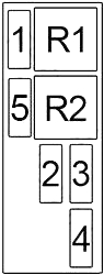
Passenger compartment relay field 1
| Number |
Relay |
| R1 | 00-03:
Horn (J4) |
| -’99:
Load reduction (J59) |
|
| R2 | 00-03:
Load reduction (J59) |
| -’99:
Horn (J4) |
|
| R3 | -’99:
Sprinkler system headlight (J39) |
| R4 | 00-03:
Fuel pump (J17) |
| -’99:
Interlock (J207) |
|
| -’99:
Starter inhibitor i reverse light (J226) |
|
| R5 | -’99:
Automatic, intermittent Wiper / Washer (J31) |
| R6 | -’99:
Fuel pump (J17) |
Passenger compartment relay field 2

| Number |
Relay |
| R1 | Folding in the mirrors (J351) |
| R2 | A / C clutch (J44) |
| R3 | Solar cell separation (J309) |
| Selector lever light (J307) | |
| Backlight LED
the selector lever (J443) |
|
| R4 | Servotronic control module (J236) |
| R5 | Interior and map / reading lamp (J91) |
| Lock control unitthe selector lever (J221) | |
| R6 | Wiper / Washer
Intermittent (J31) |
| Fog light (J5) | |
| R7 | (R7 + R12):
Front / rear control module fog lights (J512) |
| Switching daytime running lights (J89) | |
| Gaze lock (J89) | |
| R8 | Auxiliary heater (J8) |
| R9 | Bulb monitoring device (J123) |
| R10 | Entrance and floor lighting (J348) |
| R11 | Wiper / Washer
Intermittent (J31) |
| Solar cell insulation (J309) | |
| R12 | (R7 + R12):
Front / rear control module fog lights (J512) |
| Fresh air blower (J13) | |
| R13 | Automatic closing
sliding sunroof (J356) |
Passenger compartment relay field No. 3
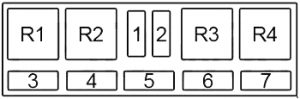
| Number |
Amperes [A] |
Description |
| 3 | 40 | Fan blowers |
| 4 | – | – |
| 5 | – | – |
| 6 | – | – |
| 7 | – | – |
| Circuit breaker | ||
| 1 | thirty | Electric seat(no.2) |
| 2 | thirty | Electric seat(memory) (no.1) |
| Relay | ||
| R1 | Engine start interlock (J207) | |
| Entrance lighting andfor legs (J348) | ||
| R2 | – | |
| R3 | Daytime running lights (J90) | |
| R4 | High beam (Litronic) (J336) | |
Passenger compartment relay field 4
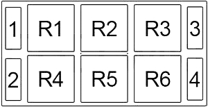
| Number |
Amperes [A] |
Description |
| 3 | – | – |
| 4 | – | – |
| Circuit breaker | ||
| 1 | thirty | Window lifting (rear) |
| 2 | thirty | Window lifting (front) |
| Relay | ||
| R1 | Warning light (J2) | |
| Indicator (J1) | ||
| R2 | (R2 + R5)Multifunction steering wheel (J453) | |
| Coolant fan controlsecond speed (J101) | ||
| (R2 + R5) Electric windows isliding roof (J139) | ||
| R3 | ABS return pump (J105) | |
| Horn (J4) | ||
| Coolant fan controlsecond speed (J101) | ||
| R4 | Automatic window closing (J261) | |
| R5 | (R2 + R5)Multifunction steering wheel (J453) | |
| Control relaycooling fan
(first speed) (J26) |
||
| (R2 + R5) Electric windows isliding roof (J139) | ||
| R6 | ABS solenoid valve (J106) | |
| Load reduction (J59) | ||
| Control relaycooling fan
(first speed) (J26) |
||
Luggage compartment fuse box
| Number |
Amperes [A] |
Description |
| 1 | twenty | Heated seats;
Right adjustment switch and the left rear seat. |
| 2 | 25 | ABS valves |
| twenty | Radio;Amplifier;
Right and left rear woofer; Power antenna. |
|
| 3 | 5/15 | Telephone |
| 4 | – | – |
| 5 | twenty | Electric seat |
| 6 | twenty | Trailer Tow |
| 7 | 25 | ABS valve |
| twenty | Radio | |
| 15 | Radio | |
| 8 | – | – |
| 9 | – | – |
| 10 | twenty | Electric seat |
| 11 | 50 | ABS control module |
| 60 | ABS control module | |
| 12 | – | – |
| 13 | 60 | Additional heater |
| 60 | Second battery | |
| 14 | – | – |
| 15 | – | – |
| 16 | – | – |
| Relay | ||
| R1 | (4 + 9) Battery isolation (J7) | |
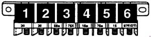
Engine compartment fuse box
| Number |
Amp [A] |
Description |
| 1 | 15 | Transmission control module |
| 2 | 15 | Drain regulator valve
EVAP canister; Intake change valve; Fuel injection control valve i leak detection pump the EVAP system. |
| 15 | ECM and fuel injectors | |
| 3 | 15 | ECM and fuel injectors |
| twenty | Purge regulator valve
EVAP canister; # 1 intake manifold regulating valve; # 2 intake manifold regulating valve; Fuel injector air control valve EVAP leak detection pump; Secondary air injection; Electro-hydraulic engine mounts; MAF sensor; Camshaft adjusting valves; (Elements control). |
|
| 4 | twenty | Terminal of ECM and ignition coil # 15 |
| 5 | ECM | |
| 5 | 15 | Transmission control module |
| Relay | ||
| R1 | Immobilizer (J341) | |
| R2 | Engine control module (J271) | |
| Secondary air injection pump (J299) | ||