

Ford Mustang Mach-E (2022) – fuse box
Ford Mustang Mach-E – fuse box diagram
Year of production: 2022.
Location of the fuse box
Body control module fuse box
The fuse box is located on the right-hand side in the passenger footwell.
Fuse box under the hood
The fuse box is on the right side of the engine compartment.
- Remove the boot lid.
- Pull the latch toward you and remove the top cover.
- Pull the connector lever up.
- Pull the connector upward to remove it.
- Pull both latches towards you and remove the fuse box.
- Turn over the fuse box and open the cover.
Installing and removing the boot lid
Rear trunk lid
- Start at the back edge of the left side.
- Pull up on the clamp locations shown to release the clamps.
- Remove the cover.
- To install, reverse the removal procedure.
Left / right luggage compartment covers
- Start at the back edge of the right (or left) page and work towards the front of the cover.
- Pull up on the clamp locations shown to release the clamps.
- Remove the cover.
- To install, reverse the removal procedure.
Vehicles built from 17/09/2021
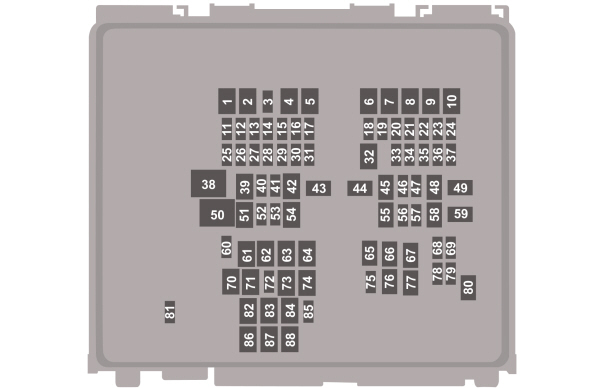
| Number | Amperes [A] | Description |
|---|---|---|
| 1 | – | Not used. |
| 2 | 40 A. | Left-hand windshield defroster. |
| 3 | – | Not used. |
| 4 | 40 A. | Right-hand windshield defroster;
Heated windshield washer nozzles. |
| 5 | – | Not used. |
| 6 | – | Not used. |
| 7 | – | Not used. |
| 8 | – | Not used. |
| 9 | – | Not used. |
| 10 | – | Not used. |
| 11 | 15 A. | Powertrain control module. |
| 12 | – | Not used. |
| 13 | 15 A. | Electric air conditioning compressor;
Active air intake grille shutter; Powertrain control module heater coolant pump; Powertrain control module heater shutoff valve. |
| 14 | 15 A. | Second drive unit (GT) transmission fluid pump. |
| 15 | – | Not used. |
| 16 | 10 A. | Battery charging control module. |
| 17 | 20 A. | Steering column lock. |
| 18 | 10 A. | Powertrain control module. |
| 19 | 10 A. | Braking system control module. |
| 20 | 5 A. | Charging port status indicator. |
| 21 | 5 A. | Front trunk cylinder relay coil. |
| 22 | 20 A. | Amplifier. |
| 23 | 20 A. | Electronic rear door on driver’s side. |
| 24 | – | Not used. |
| 25 | 25 A. | Improved headlights on the left side. |
| 26 | 25 A. | Improved headlights on the right. |
| 27 | 5 A. | Backup power supply for the PCM. |
| 28 | 5 A. | Front trunk cylinder relay coil. |
| 29 | 5 A. | DC / DC converter. |
| 30 | – | Not used. |
| 31 | 5 A. | Electronic power steering. |
| 32 | 30 A. | Body systems control module. |
| 33 | 20 A. | Advanced driver assistance system. |
| 34 | 10 A. | Headlamp control module;
Headlight on the left side; Headlight on the right. |
| 35 | 15 A. | Heated steering wheel. |
| 36 | 10 A. | First hybrid powertrain control module;
Additional power distribution box; Control module for the second hybrid powertrain. |
| 37 | 20 A. | Sound signal. |
| 38 | 40 A. | Blower motor. |
| 39 | – | Not used. |
| 40 | – | Not used. |
| 41 | 20 A. | Amplifier. |
| 42 | 30 A. | Electrically adjustable driver’s seat. |
| 43 | 40 A. | Anti-lock brake system valves. |
| 44 | 60 A. | Additional power distribution box. |
| 45 | 30 A. | Electrically adjustable passenger seat. |
| 46 | – | Not used. |
| 47 | – | Not used. |
| 48 | – | Not used. |
| 49 | 60 A. | Anti-lock brake system pump. |
| 50 | 60 A. | Fan |
| 51 | – | Not used. |
| 52 | 5 A. | USB port. |
| 53 | – | Not used. |
| 54 | – | Not used. |
| 55 | 30 A. | Heated seats. |
| 56 | 20 A. | Front trunk module. |
| 57 | 10 A. | Diagnostic connector. |
| 58 | – | Not used. |
| 59 | 40 A. | Body systems control module. |
| 60 | – | Not used. |
| 61 | 20 A. | Extra power socket. |
| 62 | – | Not used. |
| 63 | – | Not used. |
| 64 | 30 A. | Electric opening / closing of the tailgate. |
| 65 | 30 A. | Vehicle dynamics control system module. |
| 66 | – | Not used. |
| 67 | – | Not used. |
| 68 | 5 A. | Electronic battery control module. |
| 69 | 20 A. | Electronic rear door on passenger side. |
| 70 | – | Not used. |
| 71 | 20 A. | Extra power socket. |
| 72 | 20 A. | Rear window wiper. |
| 73 | – | Not used. |
| 74 | 30 A. | Windshield wiper motor. |
| 75 | – | Not used. |
| 76 | 30 A. | Heated rear window. |
| 77 | – | Not used. |
| 78 | 20 A. | Electronic front door on driver’s side. |
| 79 | 20 A. | Electronic front door on the passenger side. |
| 80 | – | Not used. |
| 81 | 10 A. | Rear window washer pump. |
| 82 | – | Not used. |
| 83 | – | Not used. |
| 84 | 40 A. | Trailer lighting module. |
| 85 | 5 A. | Rain sensor. |
| 86 | – | Not used. |
| 87 | – | Not used. |
| 88 | – | Not used. |
BATTERY FUSE BOX

| Number | Amperes [A] | Description |
|---|---|---|
| 1 | 20 A. | Front trunk |
| 2 | 20 A. | Front trunk |
FUSE BOX FOR BODY CONTROL MODULE
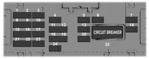
| Number | Amperes [A] | Description |
|---|---|---|
| 1 | 5 A. | A control module for a supplementary safety system. |
| 2 | 5 A. | Not used. |
| 3 | 10 A. | Not used. |
| 4 | 10 A. | Multifunction display. |
| 5 | 20 A. | Not used. |
| 6 | 10 A. | Not used. |
| 7 | 30 A. | Passenger door module. |
| 8 | 5 A. | Not used. |
| 9 | 5 A. | Auto dimming exterior mirror;
Passenger airbag disengagement indicator light. |
| 10 | 10 A. | Not used. |
| 11 | 5 A. | Electric opening / closing of the tailgate;
Control module for the tailgate open / close function, hands-free. |
| 12 | 5 A. | Anti-theft alarm;
Keyless Vehicle Entry Keyboard Switch; Driver’s side front door activation switch; Driver’s side rear door activation switch. |
| 13 | 15 A. | Not used. |
| 14 | 30 A. | Driver door module. |
| 15 | 15 A. | Not used. |
| 16 | 15 A. | Active Suspension (GT). |
| 17 | 15 A. | SYNC. |
| 18 | 7.5 amps | Wireless accessory charging module;
Driver condition monitoring; Front passenger door activation switch; Passenger’s rear door activation switch. |
| 19 | 7.5 amps | Headlamp switch assembly;
Bluetooth Low Energy module; Telematics system control unit module; Push-button starting system. |
| twenty | 10 A. | Alarm system siren. |
| 21 | 7.5 amps | Gateway module;
Heating, ventilation and air conditioning system; Gear shift module. |
| 22 | 7.5 amps | Instrument cluster;
Steering column control module. |
| 23 | 20 A. | Audio team. |
| 24 | 20 A. | Battery powered alarm siren. |
| 25 | 30 A.Installation switch | Not used. |