Kubota M100GX, M110GX, M126GX, M135GX – fuse and relay box
Diagrams of fuse and relay boxes – Kubota M100GX, M110GX, M126GX, M135GX
The scheme of the fuse box
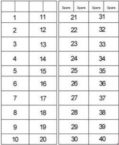
| Number | Amperes [A] | Description |
| 1 | – | – |
| 2 | 10 | ECU (suspension) |
| 3 | 5 | ECU (switch) |
| 4 | twenty | Demister |
| 5 | – | – |
| 6 | 10 | Brake lamp |
| 7 | 5 | Radio |
| 8 | 5 | Air conditioner (fan control) |
| 9 | 15 | Mat |
| 10 | 5 | Starter relay |
| 11 | – | – |
| 12 | 5 | Switch (transmission control) |
| 13 | 5 | Switch (tap control) |
| 14 | 10 | ECU (main) |
| 15 | 5 | The main counter |
| 16 | 5 | 4WD, Bi-speed, Differential lock |
| 17 | 5 | Engine control, PTO valve |
| 18 | 10 | Turn on the signal |
| 19 | 15 | Aux charger power socket |
| 20 | 5 | LCD monitor |
| 21 | 15 | Work light (cab side) |
| 22 | 15 | Work light (upper front) |
| 23 | – | – |
| 24 | – | – |
| 25 | 10 | Optional lamp |
| 26 | 15 | Work light (rear) |
| 27 | 10 | Work light (mask) |
| 28 | 15 | Seat compressor |
| 29 | 15 | Cigarette lighter socket |
| 30 | 15 | Work light (option) |
| 31 | – | – |
| 32 | 15 | The headlamp |
| 33 | thirty | Air conditioner fan motor |
| 34 | 10 | Air conditioning compressor |
| 35 | 15 | Rear lamp |
| 36 | 15 | Emergency lights |
| 37 | 10 | Dome light, radio |
| 38 | 5 | Horn |
| 39 | 5 | Lighting relay |
| 40 | 5 | Spare (ECU, meter) |
M100GX, M110GX
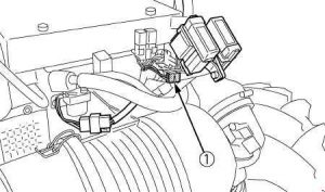
M126GX, M135GX
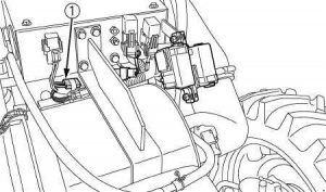
| Number | Amperes [A] | Description |
| 1 | twenty | POWER OF CRS |
M100GX, M110GX

M126GX, M135GX
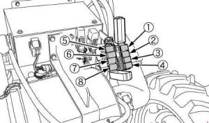
| Number | Amperes [A] | Description |
| 1 | 40 | Demister |
| 2 | thirty | Electrical outlet |
| 3 | 40 | Work light (rear) |
| 4 | 120 | M100GX, M110GX:
Engine preheating |
| 40 | M126GX, M135GX:
Work lamp (hood); Headlamp. |
|
| 5 | 40 | M100GX, M110GX:
Work light (hood) Headlamp |
| 60 | M126GX, M135GX:
Engine preheating |
|
| 6 | 40 | Compressor |
| 7 | thirty | Emergency lights |
| 8 | thirty | Main key switch |
M100GX, M110GX

M126GX, M135GX
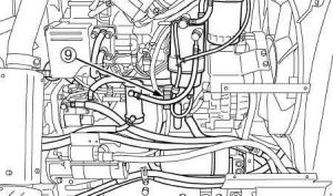
| Number | Amperes [A] | Description |
| 9 | 140 | Alternator |

