

Kubota U48-4 – fuse and relay box
Diagrams of fuse and relay boxes – Kubota U48-4
Fuse box
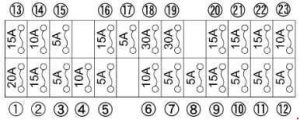
| Number | Amperes [A] | Description |
| 1 | twenty | Cab light |
| 2 | 15 | Work light |
| 3 | 5 | Counter (+ B) |
| 4 | 10 | Horn |
| 5 | 5 | Vehicle interior light |
| 6 | 10 | Alternator |
| 7 | 5 | Cab relay |
| 8 | 5 | Meter (AC) |
| 9 | 15 | ECU (AC) |
| 10 | 5 | Fuel pump |
| 11 | 5 | Lever lock |
| 12 | 5 | Starter |
| 13 | 15 | AI engine |
| 14 | 10 | Horn SW |
| 15 | 5 | ECU (+ B) |
| 16 | 15 | Light rooster |
| 17 | 5 | Air conditioning control unit (+ B) |
| 18 | 10 | Engine stop |
| 19 | thirty | Blower motor |
| 20 | 15 | Electrical outlet |
| 21 | 15 | Radio (AC) |
| 22 | 15 | Windshield washer |
| 23 | 10 | Compressor;
Air conditioning controller (AC). |
Slow-blow fuse
A slow-blow fuse is used to protect electrical circuits. If the fuse is blown, check the electrical circuits for problems, then replace it with a new compatible, slow-blow fuse.

| Number | Amperes [A] | Description |
| A | – | – |
| B | 80 | Alternator |
| C. | 50 | Main power |
| D | 50 | Cab motor stop relay (blower motor) |