

Mercedes-Benz A-Class w169 (2004-2012) – fuse box
Mercedes-Benz A-Class w169 (2004-2012) – fuse box diagram
Year of production: 2004, 2005, 2006, 2007, 2008, 2009, 2010, 2011, 2012.
The cigarette lighter fuse (power socket) on the Mercedes A-Class w169 (2004-2012) is fuse 53 in the fuse box
Fuse box in the passenger footwell
The fuse box is located in the front passenger footwell.
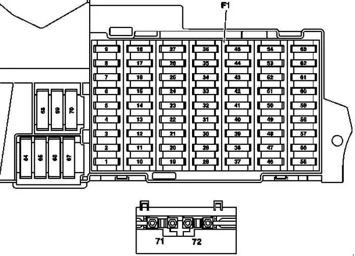
| Number |
Description |
Amperes [A] |
| 1 | Stop light switch | 10 |
| Valid for code (U62)
Light and vision package : Stop light switch. |
5 | |
| 2 | Heated rear window | 25 |
| 3 | EIS [EZS] instrument cluster control unit | 7.5 |
| 4 | EIS driver [EZS];
Electric steering wheel lock control unit. |
15 |
| 5 | Valid without code (580)
Automatic air conditioning and without code (581) Automatic comfort air conditioning: HEAT control and operating unit; Valid for code (580) Automatic air conditioning: AAC [KLA] control and service unit; Valid for code (581) comfort automatic air conditioning: Comfortable control and operating unit AAC [KLA]. |
7.5 |
| 6 | Left horn;Right horn. | 15 |
| 7 | Fuel pump relay | 25 |
| Valid for model 169.090:
DC / DC converter control unit |
5 | |
| 8 | Suspended control unit control unit | 25 |
| 9 | ESP and BAS control unit | 40 |
| 10 | Blower controller harness / interior harness connector | 40 |
| 11 | Valid for engine 266:
relay circuit 87, engine |
30 |
| Valid for engine 640:
circuit 87 relay, engine |
40 | |
| 12 | Steering column module;
Multifunction steering wheel. |
5 |
| 13 | Left front door control unit | 25 |
| 14 | Right front door control unit | 25 |
| 15 | ESP and BAS control unit | 25 |
| 16 | Data link connector;
PTS control unit. |
10 |
| 17 | Rotary light switch | 5 |
| 18 | Valid for gearbox 711, 716:
Backup lamp switch; Valid for model 169.090: Driver’s prężarki C BKGN; Energy monitoring control unit; Vacuum pump control unit 1; Vacuum pump control unit 2. |
7.5 |
| 19 | AY micromechanical rotation speed sensor | 5 |
| 20 | Restraint systems control unit | 7.5 |
| 21 | Starter relay | 30 |
| 22 | Instrument cluster | 7.5 |
| 23 | Spray nozzle heating | 7.5 |
| Valid for engine 640 as of 1.9.08:
Fuel filter condensation sensor with heating element. |
20 | |
| 24 | Electric power steering (ES) control unit | 7.5 |
| 25 | Stop light switch;
ESP and BAS control unit. |
7.5 |
| 26 | Valid for gearbox 722:
Electronic gear lever module control unit. |
7.5 |
| 27 | Valid for gearbox 722:
CVT control unit (continuously variable automatic transmission). |
10 |
| 28 | Rotary light switch | 5 |
| 29 | SAM control unit | 30 |
| 30 | Relay 87F circuit | 25 |
| 31 | Central gate controller (vehicles until 30/11/05);
Rotary light switch; Automatic light switch; Daylight sensor; Rain and light sensor. |
5 |
| 32 | Valid for engine 266:
ME-SFI [ME] control unit; Valid for model 169.090: Energy monitoring control unit. |
7.5 |
| 33 | Radio;
Radio and navigation unit; COMAND operating, display and control unit (Japan). |
15 |
| 34 | Left rear door control unit | 25 |
| 35 | Right rear door control unit | 25 |
| 36 | Cell phone separation point;
Trailer control unit. |
7.5 |
| Trailer control unit;
PTS control unit. |
10 | |
| 37 | Safety systems control unit
Front passenger seat occupancy recognition sensor; Front passenger seat occupied and child seat recognition sensor |
7.5 |
| 38 | Front cigarette lighter with ashtray illumination | 25 |
| 39 | Wiper motor | 25 |
| 40 | Suspended control unit control unit | 7.5 |
| Roof engine | 25 | |
| 41 | Liftgate wiper motor | 15 |
| 42 | Glove box lighting with switch;
Left and right cosmetic mirror lighting; Footwell lighting switch (driving school package); Pedal Operation Monitor Switch (Driving School Package); VICS + ETC supply voltage separation point (Japan). |
7.5 |
| 43 | Valid for engine 266:
connector sleeve e of terminal 87M1. |
15 |
| Valid for engine 640:
terminal connector sleeve 87M1e. |
7.5 | |
| Valid for model 169.090:
1 vacuum pump control unit, |
20 | |
| 44 | Valid for engine 266:
clamp connector sleeve 87M2e, |
15 |
| Valid for engine 640:
terminal connector sleeve 87M2e. |
20 | |
| 45 | Valid for engine 640:
CDI control unit; Valid for model 169.090: vacuum pump control unit 2. |
25 |
| 46 | Telephone control unit, (Japan);
E-net Compensator; Universal Portable CTeL Interface (UPCI [UHI]) control unit. |
7.5 |
| Bass module speaker (Japan) | 25 | |
| Amplifier for sound system | 40 | |
| Valid for model 169.090:
Charging control unit. |
5 | |
| 47 | Telephone switchboard, (Japan);
Universal Portable CTEL Interface (UPCI [UHI]); Control unit Cell phone separation point; Voice Control System (VCS [SBS]); Control unit; Valid for model 169.090: Charger 1. |
7.5 |
| 48 | ATA [EDW] / towing protection / interior protection control unit;
Alarm signal with additional battery; Valid for model 169.090: charger 2. |
7.5 |
| 49 | Top control panel;
Heated left front seat cushion; Heated left front seat cushion; Right front seat heating element; Right front seat heater. |
25 |
| 50 | CD changer;
Multimedia interface control unit; Digital television tuner; Digital audio broadcasting control unit; VICS + ETC Voltage supply separation point (Japan). |
7.5 |
| For government vehicles:
Roof light strip; Circuit connector sleeve 30. |
30 | |
| 51 | Valid for model 169.090:
Cooling fan; Low temperature coolant pump. |
10 |
| 52 | VICS + ETC voltage separation point (Japan) (vehicles up to 5/31/06);
Valid for model 169.090: Electric drive control unit. |
5 |
| Spare (vehicles from 1.6.06) | 7.5 | |
| Emergency call system control unit (USA) (vehicles up to 5/31/06) | 7.5 | |
| 53 | Rear cigar lighter with ashtray lighting
Internal socket. |
30 |
| 54 | Sound amplifier;
Bass module speaker. |
25 |
| Valid for model 169.090:
Electric drive control unit. |
5 | |
| 55 | Left front headlight (bi-xenon);
Right front headlight (bi-xenon). |
7.5 |
| Left Front Light Assembly (Hi-Xenon) | 10 | |
| 56 | Reserve | 10 |
| Right Front Light Assembly (Hi-Xenon) | 10 | |
| 57 | Trailer hitch socket (13-pin) (vehicles as of 1.6.05) | 15 |
| Audio gateway control unit (Japan) (vehicles up to 5/31/05) | 25 | |
| SDAR control unit;Emergency call system control unit (USA). | 7.5 | |
| 58 | Trailer control unit;
Valid for model 169.090: Vehicle gate control unit. |
25 |
| 59 | Trailer control unit (vehicles up to 5/31/05)
Trailer hitch socket (13-pin) (vehicles from 1.6.05). |
20 |
| Valid for model 169.090:
Battery management system control unit 1. |
5 | |
| 60 | Driver seat connector block | 20 |
| 61 | Front passenger seat connector block | 20 |
| 62 | Circuit 15 of relay (2) (SA: xenon, cellular phone) | 25 |
| 63 | Spare (vehicles up to 5/31/05) | – |
| Audio gateway control unit (Japan) (vehicles as of 1.6.05);
For government vehicles: Roof light bar. |
25 | |
| Emergency call system control unit (USA) (vehicles as of 1.6.05);
SDAR control unit. |
7.5 | |
| Valid for model 169.090:
Battery management system control unit 2. |
5 | |
| 64 | Valid for engine 266:
Air pump relay. |
40 |
| Valid for engine 640:
Engine Harness / Engine Compartment Connector; Burn time output stage. |
80 | |
| 65 | Electric power steering (ES) control unit | 80 |
| 66 | SAM control unit | 60 |
| 67 | Circuit 15R relay (2) (SE) | 50 |
| 68 | Valid for engine 266.920 and engine 266.940 with gearbox 722:
AAC with integrated control of an additional fan motor. |
50 |
| Valid for engines 640.940, 640.941, 266.960, 266.980 and for engines 266.920, 266.940 with (trailer hitch):
AAC with integrated control of an additional fan motor. |
60 | |
| 69 | Circuit 15R relay (1) | 50 |
| 70 | Circuit 15 relay (1) | 60 |
| 71 | Valid for engine 640:
PTC heating amplifier. |
150 |
| 72 | Circuit 30 connector sleeve
Special vehicle multifunction control unit (SVMCU [MSS]) (Taxi). |
60 |
| Number |
Description |
Amperes [A] |
| 80 | Reserved for special purpose vehicles | 30 |
| 81 | Reserved for special purpose vehicles | 30 |
| 82 | Reserved for special purpose vehicles | 30 |
| 83 | Reserved for special purpose vehicles | 30 |
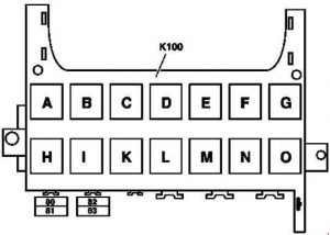
| Relay | ||
| A | Circuit 15R relay (2) (SA) | |
| B | Circuit 15R relay (1) | |
| C. | Fanfare horn relay | |
| D | Heated rear window relay | |
| E. | Stage 1/2 wiper relay | |
| F. | Wiper on / off relay | |
| G. | Circuit 15 relay (1) | |
| H. | Backup relay | |
| I | Air pump relay | |
| K. | Fuel pump relay | |
| L | Engine circuit 87 Relay | |
| M. | Starter relay | |
| N | Relay 87F circuit | |
| O | Circuit 15 of relay (2) (SA: xenon, cellular phone) | |