

Mercedes-Benz Sprinter (W906) (2006-2017) – fuse box
Mercedes Sprinter (W906) (2006-2017) – fuse box diagram
Year of production: 2004, 2005, 2006, 2007, 2008, 2009, 2010, 2011, 2012, 2013, 2014, 2015, 2016, 2017.
The cigarette lighter fuse (power socket) on the Mercedes Sprinter (W906) (2006-2017) is fuse 13 in the main fuse box.
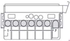
Main fuse box

| Number | Description | Amperes [A] |
| 1 | Horn | 15 |
| 2 | ESTL(electric steering lock) | 25 |
| 3 | Terminal 30 Z,vehicles with a gasoline engine,
ignition lock |
10 |
| 4 | Light switch in the center console | 5 |
| 5 | Windshield wipers | 30 |
| 6 | Fuel pump;
Terminal 87 (5) 1. |
15 10 |
| 7 | MRM(shell tube module) | 5 |
| 8 | Terminal 87 (2) | 20 |
| 9 | Terminal 87 (1)
Terminal 87 (3), gasoline powered vehicles; Terminal 87 (3), diesel vehicles. |
25 20 25 |
| 10 | Terminal 87 (4) | 10 |
| 11 | Terminal 15 R of the vehicle | 15 |
| 12 | Airbag control unit | 10 |
| 13 | Cigarette lighter;
Power socket; Radio; Cargo tailgate body, PND (Personal Navigation Device) |
15 |
| 14 | Diagnostic connection;
Light connector; A set of instruments, Disconnecting warning device before revocation; Anti-theft protection with function vehicle tracking. |
5 |
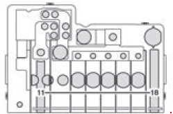
| 15 | Range of heater console reflectors for trolleys / front chamber. | 5 |
| 16 | Terminal 87 (1) Terminal 87 (3) |
10 |
| 17 | Airbag control unit | 10 |
| 18 | Terminal 15 of vehicle / brake light switch | 7.5 |
| 19 | Indoor lighting | 7.5 |
| 20 | Passenger entrance door power window switch;
Terminal 30/2 SAM (signal acquisition and activation module). |
25 |
| 21 | Engine control unit | 5 |
| 22 | Braking system (ABS) | 5 |
| 23 | Motor starter Terminal 87 (6) 1 |
20 10 |
| 24 | Diesel engine,Engine components / control unit,
(vehicles with NGT2 natural gas engine) |
10 |
| 25 | 12 V socket (center console) | 25 |
| Fuse block F55 / 1 | ||
| 1 | Driver’s door controller | 25 |
| 2 | Diagnostic connection | 10 |
| 3 | Braking system (valves) | 25 |
| 4 | Braking system (pressure pump) | 40 |
| 5 | Terminal 87 (2a) engine M272, OM651;
Terminal 87 (2a) engine OM642, OM6513. |
7.5 |
| 6 | Terminal 87 (1a) OM6426 engine;
Terminal 87 (1a) OM6516 engine; Terminal 87 (3a) engine M272, M271, OM651. |
10 7.5 7.5 |
| 7 | Headlight cleaning system | 30 |
| 8 | Anti-theft alarm system (ATA),acoustic signaling device,
acoustic signaling device with siren |
15 |
| 9 | Additional module of the turn signaling | 10 |
| Fuse block F55 / 2 | ||
| 10 | 1 DIN radio;
2 DIN radio. |
15 20 |
| 11 | Mobile phone;
Tachograph / additional recorder; Additional navigation handle. |
7.5 |
| 12 | Front blower setting,auxiliary blower for heating 1 | 30 |
| 13 | Auxiliary digital heating system control clock,
Radio receiver; DIN basic wiring; FleetBoard; Theft protection with the option vehicle tracking. |
7.5 |
| 14 | Seat heating | 30 |
| 15 | Braking system control unit | 5 |
| 16 | Heating, rear chamber heating,air conditioning of the front compartment | 10 |
| 17 | Lighting ka clearances;
Motion sensor Reading lamp and cargo lamp (courier vehicles) Load compartment lighting. |
10 7.5 10 7.5 |
| 18 | Rear compartment air conditioning system | 7.5 |
| Relays | ||
| R1 | Horn relay | |
| R2 | Windscreen wiper setting1/2 relay. | |
| R3 | Fuel pump relay;Starter relay, terminal 151; | |
| R4 | Windshield wipers on,relays turned off | |
| R5 | Starter relay, terminal 50 | |
| R6 | Relay, terminal 15 R (normally open contact) | |
| R7 | Engine control unit relay, terminal 87 | |
| R8 | Relay, terminal 15 (reinforced relay) | |
| Number | Description | Amperes [A] |
| 1 | Purge relay;
Secondary air pump for vehicles with a gasoline engine. |
80 40 |
| 2 | Air conditioning system cooling fan(cabin without partition and without system
rear chamber air conditioning); Cooling air conditioning system fan – (cabin with a partition and reinforced without air conditioning system rear compartment); Air conditioning system cooling fan – cabin; Electric exhaust fan; Starter relay, terminal 156; Starting relay not supported. |
60 40 40 25 25 |
| 3 | SAM (signal acquisition and activation module),SRB (fuse and relay module) | 80 |
| 4 | Auxiliary battery / auxiliary slowdown;
Rear compartment air conditioning system. |
150 80 |
| 5 | Terminal 30 fuse boxes,SAM (signal acquisition and activation module),
SRB (fuse and relay module) |
150 Bridge |
| 6 | Attachment point on the seat base;
Fuse box in the seat base. |
Bridge Bridge |
| 7 | Rear compartment air conditioning system;
Electric PTC booster heater. |
80 150 |

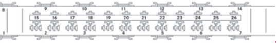
| Number | Description | Amperes [A] |
| 1 | Unassigned | – |
| 2 | SAM (signal acquisition and activation module),SRB (fuse and relay module) | 80 |
| 3 | Unassigned | – |
| 4 | Auxiliary battery input | 150 |
| 5 | Attachment point on the seat base;
Pre-fuse box; the base of the seat. |
Bridge |
| 6 | SAM (signal acquisition and activation module);
SRB (fuse and relay module); Fuse box 30. |
150 |
| 7 | Additional battery input
Connection for socket fuse (on vehicles with an extra battery) |
Bridge |
| 8 | Retarder in conjunction with a relaydisconnecting the battery | 100 |
| 9 | Extra battery | 150 |
| 10 | Hydraulic snow pump;
Hydraulic pump; Loading the tailgate; Trolley. |
250 |
| Number | Description | Amperes [A] |
| 11 | Terminal 30 – starter battery input | Bridge |
| 12 | Unassigned | – |
| 13 | Electric Booster Heater (PTC);
Rear compartment air conditioning system. |
150 80 |
| 14 | Air conditioning system cooling fan(cabin without partition and without system
rear chamber air conditioning); Cooling air conditioning system fan (cabin with a partition and reinforced without air conditioning system rear compartment); Air conditioning system cooling fan (model designation of the vehicle open in the cabin); Electric suction fan. |
60 40 40 70 |
| 15 | Unassigned | |
| 16 | Retarder not in combination with relay disconnecting the battery;
Battery disconnect relay. |
100 150 |
| 17 | Unassigned | – |
| 18 | Alternator | 300 |
Fuse box under the left front seat
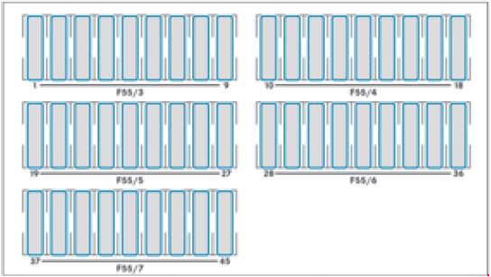
| Number | Description | Amperes [A] |
| Fuse block F55 / 3 | ||
| 1 | Adjusting the mirror, rear window defrosting | 5 |
| 2 | Rear window wiper | 30 |
| 3 | Auxiliary heating, digital timer switch;
Rear view camera; Neutral gate switch; Starting aid and all-wheel drive; Engine running; DIN socket basic wiring (roof); FleetBoard; Theft protection with rear compartment lighting i hammer emergency lighting. |
5 |
| 4 | Tachograph;
ADR / WOM / AG working speed regulator (trailer control unit). |
7.5 |
| 5 | ECO Start / control;
EGS (Electronic Transmission Control). |
5 10 |
| 6 | All-wheel drive controller;
Auxiliary oil pump. |
5 10 |
| 7 | ESM (Electronic Selector Module) | 10 |
| 8 | Loading a vehicle with a tailgate,PARKTRONIC tippers6. | 10 |
| 9 | Rear compartment air conditioning;
Compressor clutch; Back-up warning device. |
7.5 |
| Fuse block F55 / 4 | ||
| 10 | Terminal 30 body / equipment builder | 25 |
| 11 | Terminal 30 body / equipment builder | 15 |
| 12 | D +, body / hardware manufacturer | 10 |
| 13 | FSCM Fuel Pump (Fuel Sensor Control Module);
Fuel pump relay 1. |
20 15 |
| 14 | Trailer power socket | 20 |
| 15 | Trailer recognition unit | 25 |
| 16 | PARKTRONIC tire pressure monitor7 | 7.5 |
| 17 | Programmable special module (PSM) | 25 |
| 18 | Programmable special module (PSM) | 25 |
| Fuse block F55 / 5 | ||
| 19 | Top control panel without ATA iwithout rain sensor;
Top control panel with ATA system; Top control panel with rain sensor. |
5 25 25 |
| 20 | Registration lamp (courier vehicles);
Perimeter lamp; Identification lighting. |
7.5 |
| 21 | Terminal 30, body electrics(courier vehicles);
Rear window defroster without ATA (Anti-Theft Alarm system); Rear window defroster with ATA system (Anti-Theft Alarm System). |
15 30 15 |
| 22 | Rear window defroster 2;
Vehicle socket (courier vehicles). |
15 20 |
| 23 | 12 V left rear socket, luggage compartment – rear;
Electrical system: non-MB body. |
15 10 |
| 24 | 12 V socket under the base of the driver’s seat | 15 |
| 25 | 12V right rear socket, luggage / rear compartment | 15 |
| 26 | Auxiliary heating of domestic hot water | 25 |
| 27 | Electric Booster Heater (PTC);
Auxiliary air heater. |
25 20 |
| Fuse block F55 / 6 | ||
| 28 | SRB starter relay(fuse and relay module) 3-6;
Starter for electric power assistance (with the use of an additional battery). |
25 |
| 29 | Terminal 87 (7);
Gas system, natural gas engine (NGT) vehicles; SCR8 control unit, vehicles with exhaust gas treatment; Terminal 30, all-wheel drive, control unit. |
7.5 10 30 |
| 30 | Additional heat exchanger fan;Brake booster. | 15 30 |
| 31 | Heater blower on the back of the heating chamber;
Sliding door closing support system, left; Electric sliding door, left. |
30 15 30 |
| 32 | SCR8 relay power supply,vehicles with exhaust gas treatment;
KEYLESS ENTRY. |
5 10 |
| 33 | Electric sliding door, right;
Sliding door closing support system, right; ENR (level control) control unit; Compressed air suspension. |
30 15 30 30 |
| 34 | SCR8 heater 3 DEF supply tank(Diesel Exhaust Fluid)
(vehicles with exhaust gas treatment, 6 cylinders diesel 9.3); SCR8 1 DEF® heater (vehicles with diesel exhaust gas treatment). |
15 20 |
| 35 | SCR8 heater 2 hose,(vehicles with exhaust gas treatment, 6 cylinders diesel 9.3);
SCR8 2 DEF heater (vehicles with diesel exhaust gas treatment). |
15 25 |
| 36 | SCR8 heater 1 charge pump,(vehicles with exhaust gas treatment, 6 cylinders diesel 9.3);
SCR8 3 DEF heater control, (vehicles with diesel exhaust gas treatment). |
10 15 |
| Fuse block F55 / 7 | ||
| 37 | COLLECTION PRESIFICATION / FCW(Forward Collision Warning)
Blind Spot Assist / BSM (Blind Spot Monitor) |
5 5 |
| 38 | Multifunctional camera with highbeam assistant With Lane Departure Warning | 10 10 |
| 39 | body electrics (courier vehicles);
Rear compartment air conditioning system; Roof fan; Siren. |
7.5 7.5 15 15 |
| 40 | Auxiliary battery charging current | 15 |
| 41 | SAM (signal acquisition and activation module) additional battery reference voltage. | 7.5 |
| 42 | Rear compartment air conditioning system | 30 |
| 43 | Electric step / sliding door, right | 10 |
| 44 | Electric step / slide door, left | 10 |
| 45 | Electric step, control system andacoustic signaling device. | 5 |
Relays in the seat base of the left front seat
| Number | Relays | Description |
| R1 | K6 | Starter relay, right-hand drive |
| R2 | K41 | Unloading relay, terminal 15 |
| R3 | K41 / 5 | Starter relay, terminal 15 |
| R4 | K64 K110 |
Secondary air injection;
Secondary air pump relay; SCR8 relay, vehicles with exhaust gas treatment |
| R5 | K27 | Fuel pump relay |
| R6 | K23 / 1 | Blower relay, front, blower setting 1 |
| R7 | K41 / 2 | Unloading relay, terminal 15 R |
| R8 | K6 / 1 K6 |
Start relay, auxiliary battery;
Starter relay, left-hand drive. |
| R9 | K13 / 5 | Rear window defroster relay 1 |
| R10 | K13 / 6 K51 / 15 |
Rear window defroster relay 2 with ATA(Anti-Theft Alarm System);
Snow plow relay, dipped beam headlamps, left. |
| R11 | K117 / 3 K51 / 16 |
Electric step relay 1, left;
Snow plow relay, low beam, dipped beam, right. |
| R12 | K117 / 4 K51 / 17 |
Electric step relay 2, left;
Snow plow relay, high beam headlamps, left. |
| R13 | K41 / 3 K51 / 18 |
Load overload relay, terminal 15 (2);
Snow plow relay, right high beam headlamps. |
| R14 | K13 / 7 | Heated windshield relay 1 |
| R15 | K88 | Body builder relay, terminal 15 |
| R16 | K88 / 1 | Body builder relay, Terminal 61 (D +) |
| R17 | K95 K93 | Primary relay back wall load relay;
Primary load relay; Comfort relay lighting. |
| R18 | K2 | Headlight cleaning system relay |
| R19 | K51 / 10 | Sounder with siren relay |
| R20 | K39 / 3 | ATA (anti-theft alarm system) relay, horn |
| R21 | K108 K116 K23 / 2 | Perimeter / identification lighting relay;
License plate lamp relay (courier vehicles); Blower relay, heating auxiliary hot air, blower setting 1 |
| R22 | K23 / 3 | Blower relay, heatingauxiliary hot air,
blower setting 2 |
| R23 | K39 / 1 K124 / 1 |
Siren relayTerminal 61 (D +) relay, protection
anti-theft with vehicle tracking |
| R24 | K117 / 1 | Electric step relay 1, right |
| R25 | K117 / 2 | Electric step relay 2, right |
| R26 | K121 K124 |
Reverse warning device disabled by a relay;
Theft protection with vehicle tracking relay. |
Other relays
| Number | Relays | Description |
| – | K57 | Battery disconnect relay,left-hand drive vehicle |
| – | K57 / 4 | Battery disconnect relay,right-hand drive vehicle |
| – | K9 | Air conditioning system relay,auxiliary fan (duo) |
| – | K9 / 2 | Air conditioning system relay,auxiliary fan (mono) |
| – | K9 / 5 | Rear Compartment A / C Relay,
auxiliary fan |
| – | K120 | Auxiliary battery relay |