Opel Vivaro B (2014-2019) – fuse and relay box
Diagrams of fuse and relay boxes – Opel Vivaro B
Applies to vehicles manufactured in the years:
2014, 2015, 2016, 2017, 2018, 2019.
Fuses and relay boxes in the passenger compartment
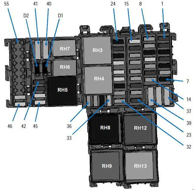
Fuse box
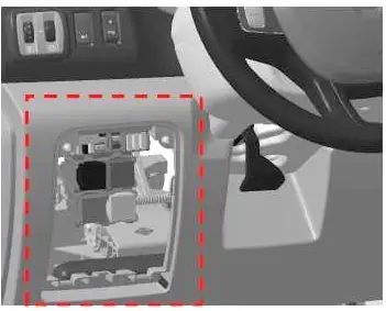
It is located on the left side of the dashboard – behind the cover on LHD vehicles.

Or in the clipboard (RHD).
Description
| F1 | 30A + battery powered rear window wiper |
| F2 | 10A Main electromagnetic horn |
| F3 | 15A + battery charging accessory socket |
| F4 | 30A + driver window motor deceleration |
| F5 | 15A + socket for rear power distribution accessories |
| F6 | 5A BCM + boot |
| F7 | 15A + after ignition power heated seats |
| F8 | 5A + EMM battery supply (after charging the ignition on VSC) AVS, AUO |
| 15A + EMM battery supply (after charging the ignition on VSC) SOP03C | |
| F9 | 5A + general current distribution |
| F10 | 15A + cigarette lighter socket or front power distribution in accessory socket |
| F11 | Battery power 25A + EMM (R daytime running lights, front position, R high beam, L low beam) |
| F12 | 5A + battery power supply for brake lights, ABS, transponder |
| F13 | 10A + time battery powered interior lighting and air conditioning |
| F14 | 5A + time battery power steering angle Stop and start the keyless vehicle |
| F15 | 25A + Ignition ON, rear window wiper, washer pump, horn |
| F 16 | 10A General + after ignition feed |
| F17 | 5A + when reverse indicator light is turned on |
| F18 | 5A + after the ignition power switch |
| F19 | 5A + after ignition feed injection, starter relay, BCM |
| F20 | 5A + supply airbag after ignition, column lock |
| F21 | 30A + passenger window switch after ignition |
| F22 | 10A + power assist pump after ignition |
| F23 | Battery brake lights 15A + EMM |
| F24 | 15A + BCM battery power (+ time battery power) |
| F25 | 10A + BCM battery operation, electronic calculating units, tire pressure monitoring system and keyless vehicle |
| F26 | 15A + BCM battery power for hazard lights and indicators |
| F27 | 25A + BCM battery power for blocking the opening elements |
| F28 | 25A + EMM battery power for L daytime running lights, rear position, L high beam, R low beam |
| F29 | 25A + EMM battery power license plate position, front and rear fog lights |
| F30 | 15A + battery powered single lever, alarm, horn |
| F31 | 5A + battery power dashboard |
| F32 | 5A + battery powered single lever |
| F33 | 20A + preparation for towbar socket with battery power |
| F34 | 15A (supplied with the tow bar) |
| F35 | 5A + battery power switch, radio, multimedia, mirrors, diagnostic socket |
| F36 | 5A + power mirror heater |
| F37 | 10A + electric mirrors with temporary battery power, additional UCE adapter |
| F38 | 40A + battery power switch tachograph |
| F39 | 40A + battery-powered wiper |
| F40 | 20A + battery current distribution relay 1 (heating, air conditioning) |
| F41 | 15A + initial equipment for power distribution, additional adaptations |
| F42 | 10A + heater to power the battery |
| F43 | 10A + supply motor with additional adaptation |
| F44 | 25A + feed motor heater |
| F45 | 25A + after ignition, supply of additional air conditioning |
| F46 | 25A + after passing ignition power for a keyless vehicle |
| F47 | 20A + EMM battery powered for no-load current distribution relay |
| F48 | – |
| F49 | – |
| F50 | – |
| F51 | – |
| F52 | – |
| F53 | – |
| F54 | – |
| F55 | – |
Relay box
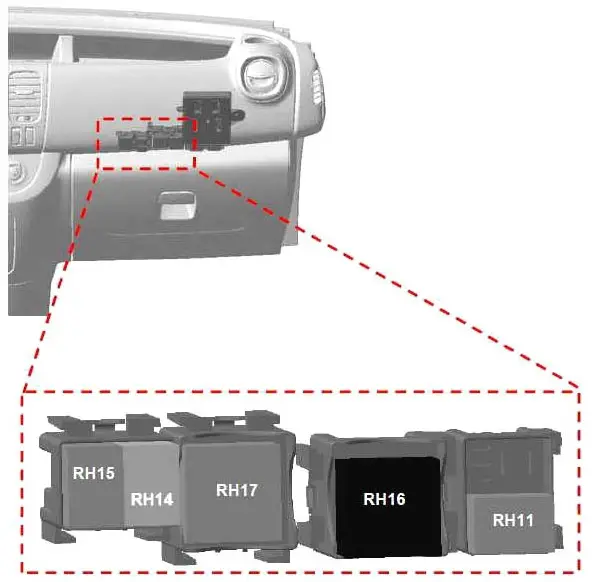
An additional relay box is located on the right side – in the glove box on the LHD.
Or behind the cover (RHD).
Description
| RH3 | 40A Windshield wiper relay |
| RH4 | 40A Relay for 2nd windshield wiper speed |
| RH5 | 40A + after ignition, rear heating and air conditioning power supply relay |
| RH6 | 20A water pump heater matrix auxiliary relay; |
| RH7 | 20A Driver’s Electric Unlock (SDO) Relay |
| RH8 | 70A + current distribution relay no. 1 |
| RH9 | 40A + current distribution relay no. 2 |
| RH11 | 20A Power windows relay |
| RH12 | 40A mirrors + rear window heating relay |
| RH13 | 40A Rear window wiper relay |
| RH14 | 20A Central door locking relay |
| RH15 | 20A Power windows relay |
| RH16 | 40A After ignition feed relay no. 2 (vehicles with handsfree card) |
| RH17 | 40A Engine running + relay |
| RH18 | – |
| RH19 | – |
| RH20 | – |
Engine compartment
It is located on the left side, next to the battery.
Description
| F1 | – | – |
| F2 | – | – |
| F3 | 25 | ABS / ESP |
| F4 | thirty | Starter |
| F5 | 70 | Passenger compartment 1 |
| F6 | 70 | Passenger compartment 3 |
| F7 | 50 | ABS / ESP |
| F8 | 60 | Passenger compartment 2 |
| F9 | twenty | Mirror heater |
| 40 | Rear window + mirror heating | |
| F10 | – | – |
| F11 | – | – |
| F12 | – | – |
| F13 | – | – |
| F14 | 15 | + air conditioning compressor with battery operation |
| F15 | 15 | Fuel pump |
| F 16 | 70 | Heater control unit |
| F17 | 60 | Heating element assembly |
| F18 | 60 | Heating element assembly |
| F19 | 40 | Engine suffix * 408 and air conditioning or 450 and heating Motor 1 fan unit |
| 50 | Engine suffix * 408 and heating or 450 and air conditioning Motor driven fan assembly 1 | |
| F20 | 40 | Engine suffix * 408 and air conditioning or 450 Motor Driven Fan Assembly 2 |
| F21 | – | – |
| F22 | – | – |
| F23 | – | – |
| F24 | – | – |
| F25 | – | – |
| F26 | 25 | Diesel fuel heater |
| F27 | twenty | Engine injection system |
| F28 | 15 | Engine injection system |
| Relay | ||
| R1 | twenty | Starting |
| R2 | twenty | Fuel pump relay |
| R3 | 40 | Injection supply relay |
| R4 | twenty | Compressor control relay |
| R5 | – | – |
| R6 | 70 | High Speed (1 motor driven fan assembly) |
| R7 | 40 | Low speed (motor driven fan assembly) |
| R8 | 40 | High speed (2 motor driven fan assembly) |
| LEDs | ||
| D1 | Air conditioning compressor | |
| D2 | – | |
Electric distribution unit
It is located near the battery itself.

- Battery protection power supply wiring
- 300A engine wiring (alternator)
- 300A Engine wiring harness (starter)
- 5A mini fuse with a cap (Start / Stop)
- 5A cab wiring (Start / Stop)
- 50A Cab Wiring (KPD & KC6 Option Conversion or Trailer Tow Hitch)
- Reserved for deliberate bodybuilder conversions
- 35A Motor Wiring (Engine Management)
- Motor connection unit
- 120A cab wiring (power steering)


