
Renault Grand Scenic (2004-2009) – fuse and relay box
Diagrams of fuse and relay boxes – Renault Grand Scenic
Applies to vehicles manufactured in the years:
2004, 2005, 2006, 2007, 2008, 2009.
Fuse box in passenger compartment
This device is located in the passenger compartment, lower left of the dashboard
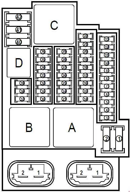
| Number | Amperes [A] | Description |
| F1 | – | Not used |
| F2 | – | Not used |
| F3 | 10 | Lighter |
| F4 | 10 | Second row accessory socket (on vehicle without key) |
| F5 | – | Not used |
| F6 | – | Not used |
| F7 | 5 | Passenger’s electric outside mirror |
| F8 | 10 | On keyless version: windshield washer pump via steering column control – audible unit to warn of component opening On vehicle with key-operated version :: windshield washer pump via steering column control – anti-theft module |
| F9 | – | Not used |
| F10 | 10 | Instrument panel (keyless vehicle version) |
| F11 | – | Not used |
| F12 | – | Not used |
| F13 | – | Not used |
| F14 | 25 | Passenger’s electric window motor |
| F15 | 5 | Brake light switch – ABS with electric ESP control unit – electric wheel speed control unit |
| F 16 | 25 | Right rear window electric motor |
| F17 | 25 | Rear left window electric motor |
| F18 | 10 | Passenger compartment light – Left luggage compartment light – Front ceiling light – Rear ceiling light – Front right ceiling mirror light – Left front ceiling mirror light – Rain sensor – Front passenger door light |
| F19 | 10 | Combined display of clock / outside temperature / radio – seat belt reminder – CAN network interface module – multimedia audio jack – anti-theft module (keyless vehicle version) |
| F20 | 5 | Automatic air conditioning control panel |
| F21 | 10 | Fuel filler flap locking engine |
| F22 | – | Not used |
| F23 | twenty | Trailer socket switch module |
| F24 | 15 | Via the electric control unit of the passenger compartment: tailgate lock – right trunk lid lighting – left trunk lid lighting |
| F25 | – | Not used |
| F26 | 10 | Electric control unit for assisting navigation |
| F27 | twenty | Radio |
| F28 | – | Not used |
| F29 | – | Not used |
| F30 | 15 | Via the passenger compartment electric control unit: Left turn signals: left rear light – left headlight – driver’s electric outside mirror Right turn signals: right rear light – right headlight – passenger electric outside mirror |
| F31 | 10 | Power supply to passenger compartment electric control module |
| F32 | thirty | Multiplexed electric driver’s door control unit |
| F33 | 25 | Via the passenger compartment electric control unit: rear right door central locking – left rear door central locking – passenger door central locking – fuel filler flap control – fuel filler flap lock motor |
| F34 | – | Not used |
| F35 | 15 | Combined clock / outside temperature / radio display – CAN interface module – Instrument panel In the vehicle with key version: – Anti-theft module |
| F36 | 15 | Diagnostic socket – Alarm warning – Electric alarm control unit – Main electromagnetic horn powered through horn relay on fuse and relay board |
| F37 | 10 | Via the electric control unit of the passenger compartment: Brake lights: left tail light – right rear light – high-level brake light |
| F38 | – | Not used |
| F39 | – | Not used |
| F40 | 40 | On the keyless version: fan assembly power module – passenger compartment fan assembly 1 (via running engine + relay) On the keyless version vehicle:: fan assembly power module – passenger compartment fan assembly 1 |
| F41 | 25 | Sunroof |
| F42 | 40 | Via heated rear window relay on passenger compartment fuse and relay box: Heated rear window – fuse F7 feed on passenger compartment fuse and relay box |
| Relays | ||
| AND | 70 | Timed shed without load + battery (no power cut-off function during the start phase) |
| b | 70 | For keyless version: Load limitation in time + battery 1 (power cut-off during the starting phase) |
| C. | 40 | Heated rear window |
| D | twenty | horn |
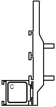
This unit is located in the passenger compartment, lower left of the dashboard, on
the steering column side.
| Number | Amperes [A] | Description |
| C. | 70 | Engine running 2 + relay for powering the fan assembly of the passenger compartment, in the keyless vehicle version with manual air conditioning |
Fuse box in the engine compartment

| Number | Amperes [A] | Description |
| 1 | 10 | Right light – front row cigarette lighter – right rear electric window – left rear electric lift – electric passenger window – right license plate light – left number plate light – right rear position lights – radio – speed limiter and cruise control switch – start button ESP on / off – rheostat switch for headlamp adjustment – central door locking switch / warning lamps – parking distance control switch – automatic transmission selector lamp – air conditioning control panel – right-hand light – left-hand light |
| 2 | 10 | Left light – left rear position light |
| 3 | 15 | Headlight washer pump |
| 4 | twenty | Left Front Fog Lamp – Right front fog lamp |
| 5 | 10 | Left headlight |
| 6 | 10 | Right headlight |
| 7 | 15 | Diagnostic socket – shift pattern control – electric parking distance control control unit – heated rear window relay control (on fuse and relay board – manual air conditioning control panel – rear view mirror – cruise control and on / off speed limiter – left headlight adjustment motor – adjustment motor right-hand headlamps – discharge bulb central electric unit – anti-theft unit |
| 8 | thirty | Anti-lock brake unit / electronic stability program control unit |
| 9 | thirty | windshield wiper motor |
| 10 | 10 | Electric Airbag / Tensioner Control Unit – Electric Steering Column Lock (Keyless Vehicle) |
| 11 | – | Not used |
| 12 | 7.5 | Electric Transmission Control Unit – Transmission Output Speed Sensor – Primary Transmission Output Speed Sensor – Multifunction Switch |
| 13 | 25 | K4M engine: electric injection control unit – petrol vapor extractor – injectors K4M838 engine: electric injection control unit – variable camshaft – additional fuel pump relay control on engine fuse and relay box – motorized throttle valve – petrol vapor canister M4R engine: variable camshaft – injectors – injectors – electric injection control unit – M4R752 and M4R753 petrol vapor absorber: variable intake camshaft – injectors – injectors – electric injection control unit – petrol vapor canister – additional control of the fuel pump relay on the fuse and relay board – motorized throttle valve F4R engine: Electric injection control unit – Injectors – Coolant pump Turbocharger bearing – Gasoline vapor canister – Exhaust gas throttle solenoid valve – Oil vapor recirculation hose heater |
| 14 | 15 | K4M engine: lower lambda probe – front lambda probe – engine camshaft intake sensor M4R engine: lower lambda probe – front lambda probe F4R engine: camshaft inlet sensor – variable inlet camshaft – oxygen sensor behind the device – oxygen sensor front |
| 15 | twenty | Electric gearbox control unit |
| 16 | 5 | Brake light switch – Passenger compartment electric control unit – Electric power steering |
| 17 | 10 | Manual gearbox TDC sensor and reversing light – Reversing light via the protection and changeover unit and via the relay on the fuse and relay plate on versions with automatic gearbox |
| 18 | 15 | Steering column lock by passenger compartment electric control unit (on keyless vehicle version) |
| 19 | 25 | Starter |
| 20 | – | Not used |
| 21 | twenty | M4R engine: fuel gauge and fuse pump – cylinder 1 pencil coil – cylinder 2 pencil coil – cylinder 3 pencil coil – cylinder 4 pencil coil – K4M and F4R engines: fuel gauge and pump fuse – cylinder 3 pencil coil – cylinder pencil coil 4 |
| 22 | 10 | Air conditioning clutch |
| 23 | 5 | ECU injection fuse |
| 24 | twenty | Left headlight |
| 25 | twenty | Right headlight |
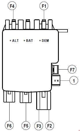
Location: located behind the battery.
| Number | Amperes [A] | Description |
| F1 | – | Not in use |
| F2 | 80 | Feed fuses F37 and F38 on fuse and relay box in passenger compartment – feed fuses F3, F4, F5, F6, F8, F11 and F40 on fuse and relay box in passenger compartment through relay on fuse and relay box in passenger compartment |
| F3 | 80 | Power supply to fuses F9, F12, F41 and F42 on fuse and relay box in passenger compartment |
| F4 | 80 | Protection and switching unit – feed fuses F23 and F24 on fuse and relay box in passenger compartment – feed fuses F1, F2, F14, F15, F16, F17, F18, F19, F20, F21 and F22 on fuse and relay box in passenger compartment through a relay on the passenger compartment fuse and the relay box |
| F5 | – | Not in use |
| F6 | 50 | ABS computer with ESP |

This unit is located in the engine coupling unit, underneath the protection and changeover unit
| Number | Amperes [A] | Description |
| F1 | – | Not in use |
| F2 | – | Not in use |
| F3 | – | Not in use |
| F4 | – | Not in use |
| F5 | 60 | Fan assembly via fan assembly high speed relay |
| F6 | twenty | Additional fuel pump via auxiliary fuel pump relay on engine fuse and relay box on K4M864, M4R752 and M4R753 engines |
| F7 | – | Not in use |
| F8 | thirty | Fan assembly through low speed fan assembly resistor through protection and switching unit – fan assembly relay control |
| F9 | – | Not in use |
| Relays | ||
| A | – | Not in use |
| b | twenty | Additional fuel pump for K4M864, M4R752 and M4R753 engines |
| C. | twenty | Reversing light on version with automatic gearbox |
| D | – | Not in use |
Location: This device is located behind the battery.
| Number | Amperes [A] | Description |
| F1 | 300 | M4R714, M4R751, M4R752, M4R753: Start protection + battery |
| 190 | K4M838, K4M864, F4R872: Start protection + battery | |
| F2 | 50 | Supply to fuses F30, F31, F32, F33, F34, F35 and F36 on the fuse and relay box in the passenger compartment |
| F3 | 80 | Supply to fuses F10, F26 and F27 on the fuse and relay box of the passenger compartment – protection and changeover unit |
| F4 | 300 | M4R714, M4R751, M4R752, M4R753: Feed fuses F1, F2, F3, F4, F5, F6, F8 and F9 on engine fuse and relay box – fuse feed on fuse panel – alternator |
| K4M838, K4M864, F4R872: Feed fuses F1, F2, F3, F4, F5, F6, F8 and F9 on the fuse and relay box of the engine – feed fuses on the fuse panel – alternator | ||
| F5 | 80 | Electric power steering |
| F6 | 35 | Protection and switching unit |
| F7 | 5 | Protection and switching unit |
| 1 | 5 | Protected + battery> protection and switching unit |
| 2 | – | Not in use |
| 3 | – | Not in use |
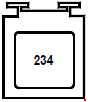
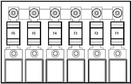
This device is located next to the fan assembly
| Number | Amperes [A] | Description |
| 234 | 70 | Engine cooling fan assembly |