
Smart Fortwo and Forfour W453 (2014-2019) – fuse and relay box
Diagrams of fuse and relay boxes – Smart Fortwo and Forfour
Applies to vehicles manufactured in the years:
2014, 2015, 2016, 2017, 2018, 2019.
The cigarette lighter (power socket) fuse on the Smart Fortwo and Forfour is fuse number 12 in the passenger compartment fuse box.
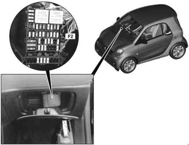
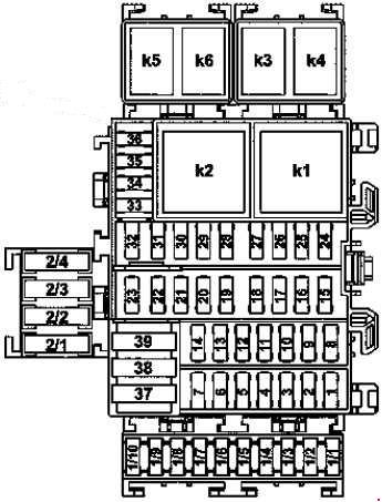
Fuse box in passenger compartment
Location of the fuse box
The fuse box is located in the storage compartment behind the cover.
| Number | Description | Amperes [A] |
|---|---|---|
| 1 | Rear roof rack electrical connection | 20 |
| 2 | Reserve | – |
| 3 | Reserve | – |
| 4 | Reserve | – |
| 5 | SAM control unit on the driver’s side | 25 |
| 6 | SAM control unit on the driver’s side | 25 |
| 7 | SAM control unit on the driver’s side | 25 |
| 8 | SAM Central Control Unit; Radio; Radio through the connector sleeve to terminal 15 R. |
15 |
| 9 | Reserve | – |
| 10 | Horn | 15 |
| 11 | Battery sensor and SAM control unit on driver’s side | 5 |
| 12 | Front cigarette lighter with ashtray illumination | 15 |
| 13 | Reserve | – |
| 14 | Internal combustion engine: Automatic transaxle protected by a connector sleeve for circuit 30; Diagnostic connector;Electric Vehicle: Fuse Circuit 30;Connector sleeve; Diagnostic connector. |
20 |
| 15 | Power supply for fuse circuit 30 connector sleeve | 15 |
| 16 | Internal combustion engine Engine electronics protected by connector sleeve for circuit 30;Electric vehicle: Power supply for fuse circuit 30;Connector sleeve. |
5 |
| 17 | Power supply protected by a connector sleeve for circuit 30 | 15 |
| 18 | Brake light switch | 10 |
| 19 | Outside mirror adjustment switch | 5 |
| 20 | Transponder coil; Electronic stability program control unit and brake light switch; Connector sleeve protected for circuit 30. |
3 |
| 21 | Light functions protected by connector sleeve for circuit 30 | 10 |
| 22 | Steering angle sensor;
Dual-clutch gearbox control unit. |
5 |
| 23 | Reserve | – |
| 24 | SAM Central Control Unit | 15 |
| 25 | SAM Central Control Unit | 10 |
| 26 | SAM Central Control Unit | 15 |
| 27 | SAM Central Control Unit | 20 |
| 28 | SAM control unit on the driver’s side | 10 |
| 29 | SAM control unit on the driver’s side | 10 |
| 30 | Combination switch; Alarm siren; Fuse circuit power supply;Connector sleeve 30 (electric vehicle). |
15 |
| 31 | Instrument cluster and additional instruments | 10 |
| 32 | Reserve | – |
| 33 | Supplemental restraint system control unit | 5 |
| 34 | Combination switch | 5 |
| 35 | Electric power steering controller | 5 |
| 36 | SAM Central Control Unit | 5 |
| 37 | SAM control unit on the driver’s side | 30 |
| 38 | A / C power solenoid switch | 40 |
| 39 | Internal combustion engine starter, via starter relay | 30 |
| 39 | Electric vehicle: blower motor |
40 |
| 1/1 | Electric vehicle: Vehicle electrical circuit 30;Connector sleeve feed. |
10 |
| 1/2 | Electric vehicle: brake booster vacuum pump control unit power electronics control |
– |
| 1/3 | Reserve | – |
| 1/4 | Sound system amplifier control unit | 20 |
| 1/5 | Engine:
Dual-clutch gearbox control unit; Electric vehicle: Electric |
5 |
| 1/6 | Left front power window motor and right front power window motor | 25 |
| 1/7 | Left electrically adjustable and heated outside mirror and right electrically adjustable and heated outside mirror | 5 |
| 1/8 | Electric vehicle: Front passenger seat heating control unit;Driver seat heating control unit. |
25 |
| 1/9 | Reserve | – |
| 1/10 | Electric vehicle: steering wheel heater relay | – |
| 2/1 | Power supply to the drive unit of the soft roof | 20 |
| 2/2 | Power supply to the drive unit of the soft roof | 20 |
| 2/3 | Reserve | – |
| 2/4 | Reserve | – |
| Relays | ||
| K1 | Heated rear window / exterior mirrors relay | |
| K2 | Electric windshield relay | |
| K3 | Roof sliding relay | |
| K4 | Headlight relay | |
| K5 | Starter relay | |
| K6 | Fanfare horn relay | |
| K. | Electric vehicle: steering wheel heater relay |
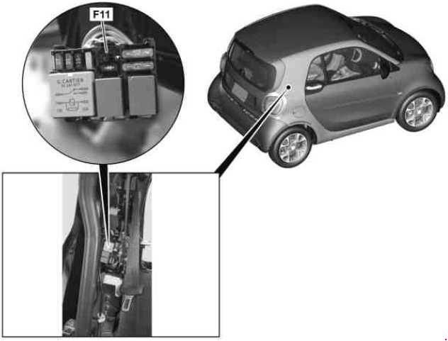
Fuse box in the engine compartment
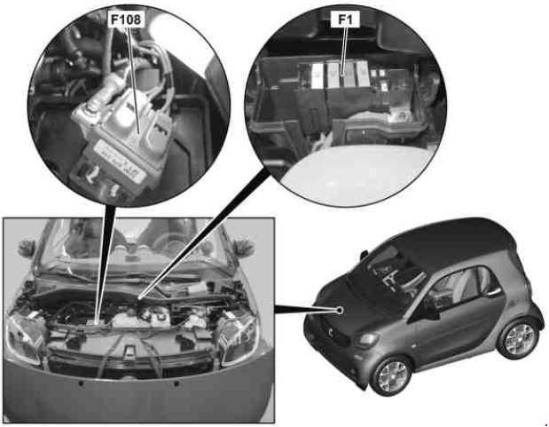
Main fuses (battery terminal)
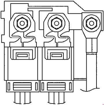
| Number | Description | Amperes [A] |
|---|---|---|
| F1 | Combustion engine: 3A electric fuse (F108f3A) and 3B electric fuse (F108f3B);Electric vehicle: Mains fuse and relay module (F1); DC / DC converter control unit. |
200 |
| F2A | Vehicle interior fuse and relay module power supply (F2); Protected by a connector sleeve for circuit 30; Connector sleeve for circuit 30. |
70 |
| F2B | Electric power steering controller | 60 |
| F3A | Vehicle interior fuse and relay module power supply (F2); Ignition switch; Secured by a connector sleeve for circuit 30; Connector sleeve for circuit 30. |
70 |
| F3B | Electronic stability program control unit | 50 |
Fuse / relay module
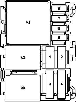
| Number | Description | Amperes [A] |
|---|---|---|
| 1 | Internal combustion engine relay module | Diode |
| 2 | Vacuum pump relay feed (for USA) | Diode |
| 3 | Fuel pump with fill level sensor and temperature sensor | 20 |
| 4 | Power supply for fuse circuit 30 connector sleeve | 25 |
| 5 | Power supply for connector sleeves for circuit 87 | 15 |
| 6 | Refrigerant compressor relay | 15 |
| 7 | Fan relay by fan | 10 |
| 8 | Dual-clutch gearbox control unit | 10 |
| Relays | ||
| K1 | Engine function circuit 87 relay | |
| K2 | Fan relay | |
| K3 | Ignition coils / fuel pump start relay | |
| K4 | – |
Fuses and Relays Assignment in Engine Compartment Fuse / Relay Module (Electric Vehicle)
| Number | Description | Amperes [A] |
|---|---|---|
| 1 | Reserve | – |
| 2 | Transmission mode recognition sensor;
Electric drive controller. |
15 |
| 3 | Electric vehicle drive motor fan relay | 40 |
| 4 | Battery cooling system coolant pump relay | 30 |
| 5 | Coolant pump for the battery cooling system | 15 |
| 6 | Applies to electric vehicles: Battery management system control unit;Electric drive control unit. |
5 |
| 7 | Power supply power electronics control unit power connector power supply sleeve | 20 |
| 8 | Circuit 87 power connector sleeve | 15 |
| Relays | ||
| K1 | Engine function circuit 87 relay | |
| K2 | Fan relay | |
| K3 | Ignition coils / fuel pump start relay | |
| K4 | Battery cooling system coolant pump relay |
Rear fuse / relay module
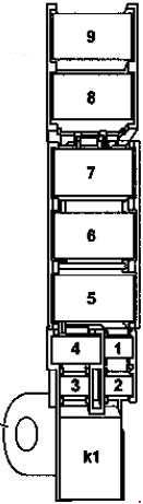
| Number | Description | Amperes [A] |
|---|---|---|
| 1 | Heated rear window above heated rear window / door mirrors relay | 30 |
| 2 | Combustion engine: Front passenger seat heater control unit;Driver seat heater control unit;Electric vehicle: Brake servo vacuum pump control unit. |
30 |
| 3 | Power supply for the control unit of the electronic stabilization program | 25 |
| 4 | Electric vehicle: Spare electric fuse 1 and electric fuse 2 |
40 |
| 4 | Internal combustion engine: sliding roof relay |
25 |
| 5 | Combustion engine fuse and relay module power supply | 60 |
| 6 | Internal combustion engine: Dual-clutch gearbox control unit; Protected by a connector sleeve for circuit 30. |
50 |
| 6 | Electric vehicle: Vehicle interior fuse and relay module power supply | 40 |
| 7 | Fan motor
Above the fan relay |
30 |
| 7 | The fan solenoid switch cooling the ICE combustion engine |
30 |
| 8 | Reserve | – |
| 9 | Combustion engine: Secondary air injection pump (for USA);Electric Vehicle: High Voltage Battery Heater; High voltage battery overheat relay. |
60 |
| K1 | Fan relay |