

Mercedes-Benz Sprinter (907) (2018-2022) – fuse box
Mercedes-Benz Sprinter – fuse box diagram
Year of production: 2018, 2019, 2020, 2021, 2022.
Fuse and relay box in the passenger footwell
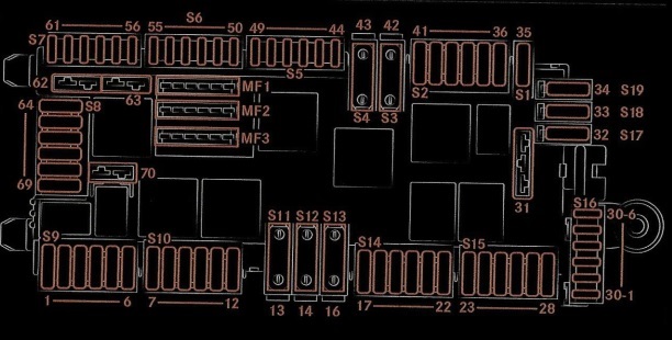
| Number | Description | Amperes [A] |
| MF1 | ||
| 15-1 | Engine control unit;
Common Powertrain Module (CPC); ESP module; Four-wheel drive module; Retarder; Pneumatic suspension. |
5A |
| MF2 | ||
| 15-2 | Feedback cable, terminal 15 relay;
Headlight range adjustment, halogen headlight; TCO tachograph; Radar sensor for active brake assist; Reversing warning device deactivation, power take-off, working speed adjustment; Connection to a DIN socket. |
5A |
| MF3 | ||
| 30-T | Multifunction camera;
TCO tachograph; Connection to DIN socket, roof; Terminal 15, undervoltage relay; Instrument cluster; Central oil pump. |
7.5A |
| S9 | ||
| 1 | Unassigned | |
| 2 | Common Powertrain Module (CPC) | 10A |
| 3 | OM642 / OM651 / M274 engine control unit | 10A |
| 4 | DIN socket, cockpit | 7.5A |
| 5 | Common Powertrain Module (CPC) | 10A |
| 6 | Radiator fan (not for OM654) | 5A |
| S10 | ||
| 7 | Automatic Transmission | 30A |
| 8 | Body controller | 30A |
| 9 | Body controller | 30A |
| 10 | Heating, SCR catalyst. | 30A |
| 11 | Ceiling control module (standard);
Ceiling control module, cab chassis; Ceiling control module, high. |
10A / 10A / 15A |
| 12 | Pump, SCR catalyst | 15A |
| S11 | ||
| 13 | Automatic gearbox NAT3 | 60A |
| S12 | ||
| 14 | ESP valves (Premium), vehicles with electromechanical parking brake;
ESP valves (Standard). |
40A / 25A |
| S13 | ||
| 16 | ESP pump | 60A |
| S14 | ||
| 17 | Body controller | 30A |
| 18 | Body controller | 30A |
| 19 | D +, bodybuilder | 10A |
| 20 | Co-driver’s door control unit | 25A |
| 21 | Driver’s door controller | 25A |
| 22 | Air suspension control unit (LFA) | 10A |
| S15 | ||
| 23 | Blower control unit | 25A |
| 24 | USB socket (cockpit, glove box);
115V / 230V converter socket. |
7.5A |
| 25 | Cigarette lighter, center console | 15A |
| 26 | Information panel socket | 15A |
| 27 | Converter socket, 115V / 230V. | 25A |
| 28 | Pre-installation of the radio;
Cargo elevator; Voltage converter antenna; Converter socket, 115V / 230V for vehicles with external battery. |
7.5A |
| S16 | ||
| 30-1 | Unassigned | |
| 30-2 | Unassigned | |
| 30-3 | Central lock | 5A |
| 30-4 | Alarm (ATA) | 5A |
| 30-5 | Unassigned | |
| 30-6 | Electronic ignition lock control unit | 10A |
| 31 | Starting, terminal 15-II relay | 25A |
| S17 | ||
| 32 | Unassigned | |
| S18 | ||
| 33 | Voltage quality sensor (SEB) | 5A |
| S19 | ||
| 34 | Electronics for interior lighting | 10A |
| S1 | ||
| 35 | Advance Caravanning (ACU) – a motorhome unit | 7.5A |
| S2 | ||
| 36 | Air conditioning control panel | 5A |
| 37 | Electric Steering Lock (ESTL) | 5A |
| 38 | Steering Column Control (SCSM) | 10A |
| 39 | Antenna;
Navigation; Twoway radio. |
10A |
| 40 | Rotating beacon | 5A |
| 41 | Radio multimedia system (C5 / NTG6), radio pre-installation | 25A |
| S3 | ||
| 42 | Unassigned | |
| S4 | ||
| 43 | Unassigned | |
| S5 | ||
| 44 | Multimedia system control panel | 5A |
| 45 | Charger bracket;
Wireless Mobile Interface (WMI). |
5A |
| 46 | Multimedia Connection Unit (MMI) | 7.5A |
| 47 | Hermes (UMTS / LTE communication module) | 5A |
| 48 | Telestar stationary heating | 5A |
| 49 | Central display | 5A |
| S6 | ||
| 50 | Auxiliary headlight, left (platform body builder) | 5A |
| 51 | Auxiliary headlight, right (platform bodybuilder) | 5A |
| 52 | Airbag control unit | 7.5A |
| 53 | Diagnostics | 5A |
| 54 | Relay power supply | 5A |
| 55 | TS engine (Diesel), engine control unit (OM651) | 7.5A |
| S7 | ||
| 57 | Soot particle sensor;
NOx sensor; Soot Particle Sensor (not for OM654) |
10A |
| 58 | Engine, exhaust gas recirculation (EGR) (OM642 / OM651);Engine (not for OM654). | 10A |
| 59 | Sensor NOx before and after the catalyst (not OM654) | 15A |
| 60 | Lambda probe | 10A |
| 61 | M274 engine;
Engine (OM642 / OM651). |
7.5A |
| H2 | ||
| 62 | Engine control unit (not for OM654) | 15A |
| 63 | Engine control unit;
Engine (M274); Engine (not for OM654). |
20A / 20A / 25A |
| S8 | ||
| 64 | Body controller | 30A |
| 65 | Body controller | 30A |
| 66 | Roof fan | 15A |
| 67 | Fuel metering control unit (FSCM) | 25A |
| 68 | Right LED headlight | 15A |
| 69 | Left LED headlight | 15A |
| H2 | 30A | |
| 70 | Windshield wipers | 30A |
Relay box in the passenger footwell
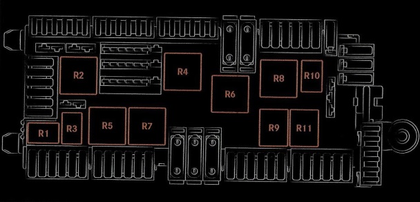
| Number | Description | Amperes [A] |
| R1 | Reserve | 30A |
| R2 | Terminal 87, engine | 50A |
| R3 | Terminal 87, common driveline module (CPC) | 30A |
| R4 | Terminal 15-I | 40A |
| R5 | Switches the windshield wipers on and off | 40A |
| R6 | Reserve | 40A |
| R7 | Windshield wipers speed | 40A |
| R8 | Terminal 50, starter | 40A |
| R9 | Terminal 15R (vehicles without additional battery) | 50A |
| R10 | Terminal 15-II | 30A |
| R11 | Terminal 15R (vehicles without additional battery) | 50A |
Fuses on the outside of the base of the driver’s seat
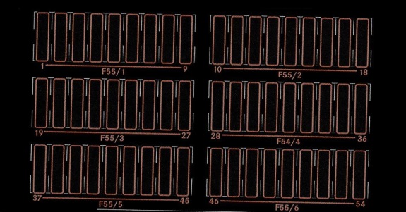
| Number | Description | Amperes [A] |
| F55 / 1 | ||
| 1 | Additional turn signal lamp | 10A |
| 2 | Rear window wiper, right | 15A |
| 3 | Four-wheel drive | 30A |
| 4 | Terminal strip for electrical connection | 25A |
| 5 | Driver’s seat adjustment unit | 25A |
| 6 | Driver seat heating unit | 10A |
| 7 | Driver lumbar support | 25A |
| 8 | Tire pressure monitoring | 5A |
| 9 | Parking assistant;
Rear Camera (RVC). |
5A |
| F55 / 2 | ||
| 10 | Trailer coupling, right (trailer socket) | 25A |
| 11 | Control unit with trailer socket | 15A |
| 12 | Trailer coupling, left (trailer socket) | 25A |
| 13 | Control unit with trailer socket | 15A |
| 14 | Multi-functional module (MPM) | 25A |
| 15 | Multi-functional module (MPM) | 25A |
| 16 | Rear chamber blower | 25A |
| 17 | Auxiliary heating (water heating) | 20A |
| 18 | Automatic gearbox, auxiliary oil pump | 15A |
| F55 / 3 | ||
| 19 | Parking heating;
Terminal 15 on extra battery. |
15A |
| 20 | Measurement voltage auxiliary battery | 5A |
| 21 | Heated rear window, left | 15A |
| 22 | Heated rear window, right | 15A |
| 23 | Tail lift / tipper vehicle (pre-installation) | 7.5A |
| 24 | Terminal strip for electrical connection | 15A |
| 25 | Roof fan relay | 5A |
| 26 | Signal special, cockpit body | 7.5A |
| 27 | Rear window heating | 30A |
| F55 / 4 | ||
| 28 | Sliding door, left;
Electric sliding door, left. |
15A / 30A |
| 29 | Sliding door, right;
Electric sliding door, right. |
15A / 30A |
| 30 | Antenna switch box | 5A |
| 31 | Automatic Transmission | 7.5A |
| 32 | Automatic Transmission | 10A |
| 33 | Brake servo | 30A |
| 34 | Siren relay;
Preparation for a motorhome. |
15A / 30A |
| 35 | Rotating beacon with siren;
Preparation for a motorhome. |
15A / 30A |
| 36 | Preparation for a motorhome | 30A |
| F55 / 5 | ||
| 37 | Electric step, left | 10A |
| 38 | Electric step, right | 10A |
| 39 | Warning buzzer;Electric step, right and left. | 5A |
| 40 | Automatic transmission (NAT2) | 10A |
| 41 | Terminal 15, special signal | 5A |
| 42 | Rear Camera (RVC);
Interior mirror with monitor for rear view. |
5A |
| 43 | Nest, cabin | 15A |
| 44 | Seat, D pillar, left | 15A |
| 45 | Seat, D pillar, right | 15A |
| F55 / 6 | ||
| 51 | USB port, left | 7.5A / 5A |
| 52 | USB port, right | 7.5A / 5A |
Fuses in the base of the driver’s seat and in the battery box

| Number | Description | Amperes [A] |
| F150 / 1 (MFB-1) | Battery box | |
| 1 | Battery sensor | |
| 2 | Unassigned | MIDI |
| 3 | Main fuse box (MFB-2) | Rail |
| 4 | Energy Distribution Center, Terminal 30 (F30-1 – F30-6) | 50A |
| 5 | PTC booster heater | 125A |
| F150 / 4 (MFB-2) | ||
| 1 | Terminal 30T, Fuse Box, Driver Seat Base (F55 / 1-F55 / 6) | 125A |
| 2 | Electric control | 125A |
| 3 | Alternator | 300A |
| 4 | Alternator | 400A |
| 5 | Energy Distribution Center (PDC), FB-P | 175A |
| 6 | Glow output stage (GZE) | 80A |
| 7 | Radiator fan (not for OM654);
Engine radiator fan; Radiator fan (not for OM654). |
40A / 70A / 80A |
| 8 | Motorhome main fuses | 100A |
| 9 | Unassigned | – |
| 10 | Air conditioning, rear compartment | 100A / 50A / 25A |
| 11 | Extra battery / Battery cut-off relay;
Retarder without additional battery. |
150A / 100A |
| 12 | Air Suspension (LFA) | 40A |
| 13 | Windshield heating | 80A |
| F150 / 5 (MFB-ZB) | ||
| 1 | Retarder | 100A |
| 2 | Tail lift / tipper vehicle (preparation) | 250A |
| 3 | Extra battery | |
| 4 | Battery cut-off relay | 150A |
| 5 | Socket, converter | 60A |
| 6 | Auxiliary heating | 25A |
| F59 / 1 and F59 / 2 | ||
| 1 | Heated windscreen, left | 40A |
| 2 | Heated windshield, right | 40A |
Relays

| Number | Description | Amperes [A] |
| 1 | Windshield heating | |
| 2 | Terminal 15 | |
| 3 | Heated rear window | |
| 4 | Sockets, rear | |
| 5 | Interior lighting | |
| 6 | Not used | |
| 7 | Not used | |
| 8 | Not used | |
| 9 | Not used | |
| 10 | Not used | |
| 11 | Not used | |
| 12 | Not used | |
| 13 | Not used | |
| 14 | Not used | |
| – | Mini-relays | – |
| 15 | Right-hand rear wiper | |
| 16 | The body of the manufacturer’s terminal strip | |
| 17 | Switch, reverse tell-tale | |
| 18 | Roof fan | |
| 19 | Additional oil pump | |
| 20 | Electric step, right 1 | |
| 21 | Electric step, right 2 | |
| 22 | Electric step, left 1 | |
| 23 | Electric step, left 2 | |
| 24 | Siren | |
| 25 | Rotating beacon with siren | |
| 26 | Load elevator |