

Kubota L3240, L3540, L4240, L5740 – fuse and relay box
Diagrams of fuse and relay boxes – Kubota L3240, L3540, L4240, L5740
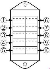
Fuse box
ROPS
CABIN

| Number | Amperes [A] | Description |
| 1 | 7.5 | Alternator |
| 2 | 15 | Headlamps |
| 3 | 15 | ROPS: Hazard warning lights |
| 20 | CAB: Hazard warning lights | |
| 4 | 5 | Plate |
| 5 | 5 | T / M controller 1 |
| 6 | 10 | ROPS: Work light |
| 15 | CAB: Work light | |
| 7 | 5 | ROPS: brake light switch |
| 8 | 10 | T / M controller 2 |
| ROPS, MT: OPC driver | ||
| 9 | 5 | A key stop |
| 10 | 30 | Starter relay |
| 11 | 10 | CAB: Dome lamp |
| 12 | 20 | CAB: Air conditioning blower |
| 13 | 5 | CABIN: Cassette radio |
| 14 | 20 | CAB: Cigarette lighter |
| 15 | 7.5 | CAB: Air conditioning compressor |
| 16 | 30 | CAB: Doormat |
| 17 | 15 | Cab: Blinker |
| 18 | 30 | CAB: Demister |
| Number | Amperes [A] | Description |
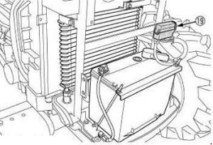
| 19 | Check the circuit for the wrong battery |