

Kubota L3301, L3901 – fuse and relay box
Diagrams of fuse and relay boxes – Kubota L3301, L3901
Fuse box
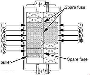
| Number | Amperes [A] | Description |
| 1 | 5 | Engine ECU (ignition key) |
| 2 | 5 | Main ECU (ignition key) |
| 3 | 5 | Gauge panel (ignition key) |
| 4 | 10 | Combination switch |
| 5 | 5 | Work light |
| 6 | 5 | Starter relay |
| 7 | twenty | Engine ECU (battery) |
| 8 | 5 | Main ECU (battery) |
| 9 | 5 | Meter panel (battery) |
| 10 | 10 | Emergency lights |
Slow-blow fuse

| Number | Amperes [A] | Description |
| 1 | 40 | Charger |
| 2 | 50 | BATTERY |