

Mercedes-Benz GLC X253/C253 (2015-2019…) – fuse box
Mercedes-Benz GLC x253 – fuse box diagram
Year of production: 2015, 2016, 2017, 2018, 2019.
GLC250, GLC300, GLC350, GLC43, GLC63
The cigarette lighter fuse (power socket) on the Mercedes GLC x253 is # 445 (trunk socket), # 446 (front cigarette lighter, internal power socket) and # 447 (right rear center console socket) in the trunk.
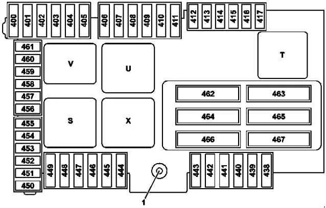
Fuse box in the trunk
Option 1
Variant 2
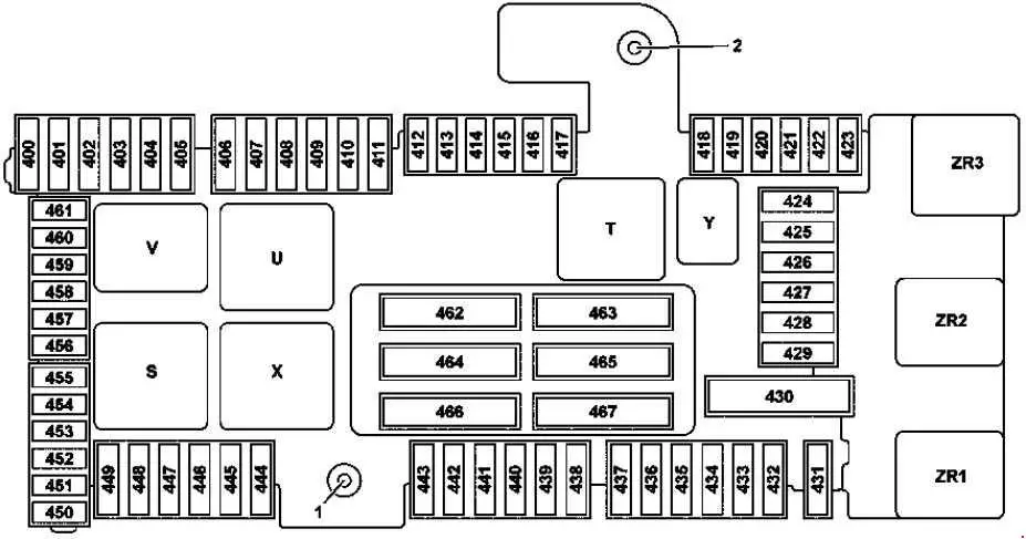
1 – Terminal 30 “E1”
power supply 2 – Terminal 30g “E2” power supply
| Number | Amperes [A] | Description |
| 400 | 25 | BlueTEC: AdBlue ® control unit |
| 401 | 15 | BlueTEC: AdBlue ® control unit |
| 402 | 20 | BlueTEC: AdBlue ® control unit |
| 403 | 30 | Valid until November 30, 2015:
Front passenger seat, semi-electric seat adjustment switch |
| 25 | Valid from 01/12/2015:
Front passenger seat, semi-electric seat adjustment switch |
|
| 404 | 30 | Valid until November 30, 2015:
Driver seat, semi-electric seat adjustment switch |
| 25 | Valid from 01/12/2015:
Driver seat, semi-electric seat adjustment switch |
|
| 405 | – | Reserve |
| 406 | 30 | Left front door control unit |
| 407 | – | Reserve |
| 408 | 30 | Right rear door control unit |
| 409 | – | Reserve |
| 410 | 5 | Stationary radio receiver for remote control of the heater;
Antenna switch for telephone and stationary heater. |
| 411 | 30 | Left front reversible emergency tension retractor |
| 412 | 7.5 | Hybrid:
Battery management system control unit |
| 413 | 5 | Trunk lid control unit |
| 414 | 5 | Tuner module |
| 415 | 5 | Camera cover control unit;
Perfume sprayer generator. |
| 416 | 7.5 | Antenna amplifier / compensator for a mobile phone system
Mobile phone contact plate |
| 417 | 5 | 360 ° camera control unit;
Reversing camera. |
| 418 | 5 | Rear seat heating control unit;
AIRSCARF control unit. |
| 419 | 5 | Front passenger seat lumbar support adjustment control unit |
| 420 | 5 | Driver’s seat lumbar support adjustment control unit |
| 421 | – | Reserve |
| 422 | – | Reserve |
| 423 | 5 | Sound system amplifier control unit |
| 424 | 15 | AIR BODY CONTROL Plus control unit;
Valid for engine 276: Engine sound control unit. |
| 425 | – | Reserve |
| 426 | – | Reserve |
| 427 | – | Reserve |
| 428 | – | Reserve |
| 429 | – | Reserve |
| 430 | – | Reserve |
| 431 | 25 | Multifunctional control unit for a special purpose vehicle |
| 432 | 25 | Multifunctional control unit for a special purpose vehicle |
| 433 | 20 | Trailer recognition control unit |
| 434 | 30 | Trailer recognition control unit |
| 435 | 25 | Trailer recognition control unit |
| 436 | 15 | Trailer recognition control unit |
| 437 | 25 | Trailer recognition control unit |
| 438 | 30 | DC / AC converter control unit |
| 439 | – | Reserve |
| 440 | 30 | Rear seat heating control unit;
AIRSCARF control unit. |
| 441 | 30 | AIRSCARF control unit |
| 442 | 25 | Fuel system control unit |
| 443 | 30 | Right front reversible emergency tensioner |
| 444 | 15 | Tablet PC electrical connector |
| 445 | 15 | Trunk socket |
| 446 | 15 | Front cigarette lighter with ashtray lighting;
Vehicle interior power socket. |
| 447 | 15 | 12V socket in the right center console |
| 448 | 10 | Valid for transmission 722, 725:
Ratchet capacitor |
| 449 | 5 | Valid for engine 626:
Fuel filter element with integrated heater; Hybrid: Sound generator. |
| 450 | 5 | Rear SAM control unit |
| 451 | 5 | Fuel system control unit;
BlueTEC: AdBlue® control unit . |
| 452 | 5 | Integrated radar sensor for the outer right rear bumper; Integrated radar sensor for the outer left rear bumper; Center rear bumper radar sensor; Outside Right Rear Bumper Radar Sensor; Outside Left Rear Bumper Radar Sensor. |
| 453 | 5 | Left front bumper radar sensor;
Right front bumper radar sensor; COLLISION PREVENTION ASSIST driver. |
| 454 | 7.5 | Valid for transmission 722:
In the fully integrated transmission control unit |
| 5 | BlueTEC:
The control unit AdBlue ® |
|
| 455 | 5 | DC / AC converter control unit |
| 456 | 5 | Front long range radar sensor;
DISTRONIC electric controller. |
| 457 | 5 | Hybrid: Power electronics control unit;DC / DC converter control unit; Power electronics control unit. |
| 458 | 5 | Rear switch module |
| 459 | 5 | Hybrid:Charger |
| 460 | 10 | KEYLESS-GO control unit |
| 461 | 5 | FM 1, AM, CL [ZV] and KEYLESS-GO antenna amplifier |
| 462 | 40 | Sound system amplifier control unit |
| 463 | 30 | Rear window heating via rear window anti-interference capacitor |
| 464 | 40 | Tailgate control unit. Liftgate control unit |
| 465 | 40 | Rear SAM control unit |
| 466 | 40 | Rear SAM control unit |
| 467 | 40 | Valid for engine 626:
Fuel filter element with integrated heater |
| Relay |
||
| S | Vehicle interior relay 15 |
|
| T. | Rear window heater relay | |
| U | Second row cup holder and socket relay | |
| V | BlueTEC:
AdBlue® relay |
|
| X | 1st row of seats / trunk refrigerator box and sockets relay | |
| Y | Spare relay | |
| ZR1 | Valid for engine 626:
Fuel filter heater relay |
|
| ZR2 | Backup relay | |
| ZR3 | Backup relay | |
Fuse box in the passenger footwell

| Number | Amperes [A] | Description |
| 301 | 5 | Hybrid:
Pyrofuse through a high voltage disconnect device |
| 302 | 30 | Right front door control unit |
| 303 | 30 | Left rear door control unit |
| 304 | 20 | Valid for transmission 722:
Intelligent servo module for DIRECT SELECT (A80) |
| 305 | 30 | Driver seat controller;
Driver seat heating controller; Front seat heating control unit. |
| 306 | 30 | Front passenger seat control unit;
Front passenger seat heating control unit; Front seat heating control unit. |
| 307 | – | Reserve |
| 308 | 30 | USA version:
Electrical connector for the electric brake control |
| 309 | 10 | Emergency call system control unit |
| 5 | HERMES control unit;
Telematics services communication module. |
|
| 310 | – | Reserve |
| 311 | 10 | Booster electronic blower control |
| 312 | 10 | Suspended control unit control unit |
| 313 | 10 | Hybrid:
DC / DC converter control unit |
| 314 | – | Reserve |
| 315 | 5 | Powertrain control unit;
Valid for diesel engine: CDI control unit; Valid for gasoline engine: ME-SFI control unit. |
| 316 | 7.5 | Supplementary restraint system control unit |
| 317 | 7.5 | Panoramic sunroof control module;
Sliding roof control module. |
| 318 | 20 | Stationary heater control unit |
| 319 | 5 | Hybrid:
High voltage PTC heater |
| 320 | 15 | AIR BODY CONTROL control unit |
| 321 | 5 | Japanese version:
Dedicated control unit for short-range communication. |
| 322 | 20 | Main unit |
| 323 | 5 | Parking system control unit |
| MF1 / 1 | 7.5 | Audio / COMAND display Audio fan motor |
| MF1 / 2 | 7.5 | Multi-functional stereo camera;
Multifunctional monaural camera. |
| MF1 / 3 | 7.5 | Rain and light sensor with additional functions;
Driver on the control panel. |
| MF1 / 4 | 7.5 | Driver seat controller;
Driver seat heating controller; Front seat heating control unit. |
| MF1 / 5 | 7.5 | Front passenger seat control unit;
Front passenger seat heating control unit; Front seat heating control unit. |
| MF1 / 6 | 7.5 | Steering wheel lamp module control unit |
| MF2 / 1 | 5 | Left front reversible emergency tension retractor |
| MF2 / 2 | 5 | Audio / COMAND control panel;
Touchpad. |
| MF2 / 3 | 5 | Right front reversible emergency tensioner |
| MF2 / 4 | 5 | Heads-up display |
| MF2 / 5 | 5 | Multimedia connection unit |
| MF2 / 6 | 5 | Hybrid:
electric refrigerant compressor |
| MF3 / 1 | 5 | Feedback line, clamp 30g, front SAM control unit |
| MF3 / 2 | 5 | Radar sensors control unit |
| MF3 / 3 | – | Reserve |
| MF3 / 4 | 5 | A group of buttons on the driver’s side instrument panel |
| MF3 / 5 | 5 | Rear air conditioning control unit |
| MF3 / 6 | 5 | Rear air conditioning control unit |
Fuse box on the dashboard

| Number | Amperes [A] | Description |
| 200 | 50 | Front SAM control unit |
| 201 | 40 | Front SAM control unit |
| 202 | 5 | Alarm siren |
| 203 | 20 | Valid with gearbox 716:
Electric steering lock |
| 204 | 5 | Diagnostic connector |
| 205 | 7.5 | Electronic ignition lock control unit |
| 206 | 5 | Analog clock |
| 207 | 15 | Climate control unit |
| 208 | 7.5 | Instrument cluster |
| 209 | 5 | Climate control of the operating unit of the unit;
Top control control panel. |
| 210 | 10 | Steering wheel lamp module control unit |
| 211 | 25 | Reserve |
| 212 | 5 | Reserve |
| 213 | 5 | Electronic stability program control unit |
| 214 | 30 | Reserve |
| 215 | – | Reserve |
| 216 | 7.5 | Lamp in the glove box |
| 217 | 5 | Japanese version:
Dedicated control unit for short-range communication |
| 218 | 7.5 | Supplementary restraint system control unit |
| 219 | 5 | Mass detection system (WSS) control unit |
| 220 | – | Reserve |
| Relay | ||
| F. | Relay, circuit 15R | |
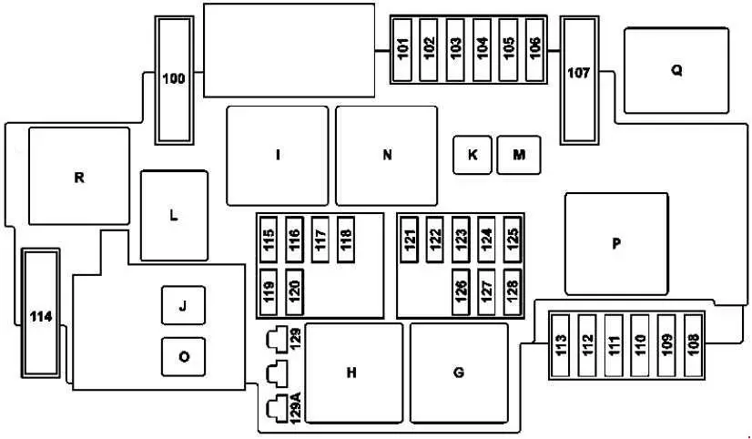
Fuse box in the engine compartment
| Number | Amperes [A] | Description |
| 100 | 40 | Hybrid:Vacuum pump |
| 101 | 15 | Connecting sleeve, circumference 87/2 |
| 102 | 20 | Connecting sleeve, circumference 87/1 |
| 103 | 15 | Connecting sleeve, circumference 87/4 |
| 104 | 15 | Connecting sleeve, circumference 87/3 |
| 105 | 15 | Valid for gearbox 722.9 (except 722.930):
Automatic transmission auxiliary oil pump control unit |
| 106 | – | Reserve |
| 107 | 60 | Valid with engine 274.9:
Electric coolant pump |
| 108 | 20 | Static LED headlight:
Right front headlight; High-performance LED headlight, dynamic LED headlight: |
| 109 | 30 | Wiper motor |
| 110 | 20 | Static LED headlight:
Left front headlight; High-performance LED headlight, dynamic LED headlight: |
| 111 | 30 | Starter |
| 112 | 15 | Hybrid:
accelerator pedal sensor |
| 113 | – | Reserve |
| 114 | 40 | AIR BODY CONTROL compressor |
| 115 | 15 | Left horn and right horn |
| 116 | – | Reserve |
| 117 | – | Reserve |
| 118 | 5 | Hybrid:
Electronic stability program control unit |
| 119 | 15 | Circuit 87 C2 connector sleeve |
| 120 | 5 | Circuit 87 Connector C1 |
| 121 | 5 | Electronic stability program control unit |
| 122 | 5 | CPC relay |
| 123 | – | Reserve |
| 124 | – | Reserve |
| 125 | 5 | Front SAM control unit |
| 126 | 5 | Powertrain control unit;
Valid for diesel engine: CDI control unit; Valid for gasoline engine: ME-SFI control unit. |
| 127 | 5 | Hybrid:
Voltage decay limiter |
| 128 | 5 | Left front lamp assembly and exterior light switch |
| 129 | 30 | Hybrid:
Starter circuit 50 relay |
| 129A | 30 | Hybrid:
Starter circuit 50 relay |
| Relay |
||
| G. | Relay 15 in the engine compartment |
|
| H. | Starter relay 50 | |
| I | Hybrid:
Vacuum pump relay (+) |
|
| J. | CPC relay | |
| K. | Valid for the gearbox 722.9 (except 722.930):
Oil pump relay |
|
| L | Horn relay | |
| M. | Wiper park position heater relay | |
| N | Relay circuit 87M. | |
| O | Hybrid:
Starter circuit 15 relay |
|
| P. | Valid with engine 274.9:
Coolant pump relay |
|
| Q | Hybrid:
Vacuum pump relay (-) |
|
| R | AIR BODY CONTROL relay | |
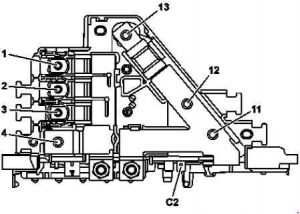
Prefuse Box in the engine compartment
Option 1
Variant 2

F32 / 3k1 – Decoupling relay
| Number | Amperes [A] | Description |
| 1 | – | Reserve |
| 2 | 100 | Valid for a diesel engine:
glow power level |
| 3 | 60 | Engine fuse and relay module |
| 4 | – | Connecting the on-board battery of the electrical system |
| 5 | 150 | Engine fuse and relay module |
| 6 | 125 | Left fuse and relay module |
| 7 | 80 | Fan motor (600W / 850W) |
| 8 | 125 | Electric power steering control unit |
| 9 | 150 | Fan motor (1000 W) |
| 10 | 200 | Pre-box inside the vehicle |
| 11 | – | Reserve |
| 12 | – | Hybrid:
Power electronics control unit; With 651.9 engine and USA version: Catalyst heater control unit. |
| 13 | 400 | Alternator |
| C1 | – | Hybrid:
decoupling relay |
| C2 | – | Hybrid:
circuit 31 |
| C3 / 1 | 40 | Electronic stability program control unit |
| C3 / 2 | 60 | Electronic stability program control unit |
Inner pre-box

F32 / 4k2 – Relay for shutting down the closed circuit
| Number | Amperes [A] | Description |
| 1 | – | Engine compartment pre-fuse box |
| 2 | 150 | Hybrid:Additional battery relay for the ECO start / stop function |
| 3 | 40 | Blower regulator |
| 4 | – | Reserve |
| 5 | 150 | Valid for diesel engine:
PTC heater amplifier |
| 6 | 80 | Fuse box on the right A pillar. |
| 7 | 150 | Rear fuse and relay module |
| 8 | – | Reserve |
| 9 | – | Reserve |
| 10 | 60 | Valid for transmission 725 (except GLC 350 e 4Matic):
In the fully integrated transmission control unit |
| 100 | GLC 350 e 4Matic:
In the fully integrated transmission control unit |
|
| 11 | – | Reserve |
| 12 | 40 | Rear fuse and relay module |
| 13 | 50 | Fuse box on the right A pillar. |