

Mercedes-Benz Vito III W447 (2014-2022) – fuse and relay box
Diagrams of fuse and relay boxes – Mercedes-Benz Vito W447
Applies to vehicles manufactured in the years:
2014, 2015, 2016, 2017, 2018, 2019, 2020, 2021, 2022.
The electrical fuses in the vehicle are used to disconnect damaged electrical circuits. Activation of the fuse causes the switching off of the components connected to the given circuit and the disappearance of the appropriate functions.
Blown fuses must be replaced with fuses of the same parameters as given in the following lists. The fuse parameters can be identified by the color and the printed ampere numbers. Advice in this regard is provided by all professional services.
If the new fuse blows again after inserting it, have the cause of the fault determined and rectified by a specialist workshop.
Fuses and relays are located in various fuse boxes:
-
Engine compartment fuse box (PDC-E)
-
Fuse box in passenger footwell (PDC-P)
-
Fuse box in passenger footwell at the A-pillar (PDC-F)
-
Rear fuse box (PDC-R)
-
Pre-fuse socket next to the starter battery in the right-hand front seat box
Have the fuses in the pre-fuse socket and relays in the fuse boxes replaced by a qualified service center.
Before replacing the fuse
- Apply the parking brake.
- Vehicles with automatic transmission: Place the transmission in position P .
- Vehicle with manual gearbox: Engage neutral position.
- Switch off all electrical consumers.
- Turn the key to position 0 and remove from the ignition.
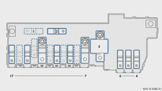
Fuse box in the engine compartment
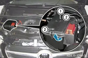
- Opening: Open the bonnet. When opening the bonnet, follow the safety instructions in the vehicle’s operating manual.
- Use a dry cloth to collect any moisture from the fuse box.
- Open the clamps 2 and remove from the fuse box.
- Tilt the cover 1 in the upward direction of the arrow and remove it.
- Closing: Check that the gasket is seated correctly on the cover 1.
- Hook cover 1 at the rear and lower it.
- Place clamps 2 on the fuse box and close.
- Close the bonnet (see vehicle owner’s manual).
Fuses
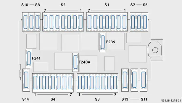
90 ° inverted view
Fuse holder S1
|
Number
|
Description
|
Fuse
|
Amperes [A]
|
|---|---|---|---|
|
1
|
ESP valves
|
F204
|
25 A.
|
|
2
|
Horn
|
F205
|
15 A.
|
|
3
|
Engine control module
|
F206
|
5 A.
|
|
4
|
Automatic transmission control module
|
F207
|
25 A.
|
|
5
|
unassigned
|
F208
|
–
|
|
6
|
unassigned
|
F209
|
–
|
|
7
|
unassigned
|
F210
|
–
|
Fuse holder S2
|
Number
|
Description
|
Fuse
|
Amperes [A]
|
|---|---|---|---|
|
1
|
unassigned
|
F211
|
–
|
|
2
|
Terminal 87 (4)
|
F212
|
15 A.
|
|
3
|
Terminal 87 (2)
|
F213
|
15 A.
|
|
4
|
Terminal 87 (3)
|
F214
|
10 A.
|
|
5
|
Terminal 87 (1)
|
F215
|
20 A.
|
|
6
|
Engine control module
|
F216
|
5 A.
|
|
7
|
unassigned
|
F217
|
–
|
Fuse holder S3
|
Number
|
Description
|
Fuse
|
Amperes [A]
|
|---|---|---|---|
|
1
|
Headlight range corrector, left-hand side
|
F229
|
5 A.
|
|
2
|
ESP
|
F230
|
5 A.
|
|
3
|
Headlight range corrector, right-hand side
|
F231
|
5 A.
|
|
4
|
unassigned
|
F232
|
–
|
|
5
|
Fuel filter heating
|
F233
|
25 A.
|
|
6
|
unassigned
|
F234
|
–
|
|
7
|
unassigned
|
F235
|
–
|
Fuse holder S4
|
Number
|
Description
|
Fuse
|
Amperes [A]
|
|---|---|---|---|
|
1
|
unassigned
|
F222
|
–
|
|
2
|
unassigned
|
F223
|
–
|
|
3
|
COLLISION PREVENTION ASSIST / DISTRONIC PLUS
|
F224
|
7.5 amps
|
|
4
|
unassigned
|
F225
|
–
|
|
5
|
Engine radiator fan / radiator shutter
|
F226
|
5 A.
|
|
6
|
Automatic transmission control module
|
F227
|
10 A.
|
|
7
|
Additional oil pump (ZÖP)
|
F228
|
15 A.
|
Fuse holders S5 to S14
|
Number
|
Description
|
Fuse
|
Amperes [A]
|
|---|---|---|---|
|
S5
|
Anti-theft alarm siren
|
F201
|
5 A.
|
|
S6
|
Auxiliary heating control module
|
F202
|
20 A.
|
|
S7
|
HLI LED Headlamp Control Module (Headlamp Functions)
|
F203
|
20 A.
|
|
S8
|
ESP control module
|
F218
|
5 A.
|
|
S9
|
unassigned
|
F219
|
–
|
|
S10
|
unassigned
|
F220
|
–
|
|
S11
|
unassigned
|
F238
|
–
|
|
S12
|
ESP pump
|
F237
|
40 A.
|
|
S13
|
The module for reading signals and implementing CBC commands 2
|
F236
|
40 A.
|
|
S14
|
LCU LED headlight control module (LED main lights)
|
F221
|
30 A.
|
Additional fuses on the relay board
|
Number
|
Description
|
Fuse
|
Amperes [A]
|
|---|---|---|---|
|
–
|
Windshield wipers
|
F239
|
30 A.
|
|
–
|
Starter, terminal 50
|
F240A
|
25 A.
|
|
–
|
unassigned
|
F241
|
–
|
Relays
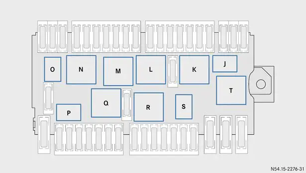
90 ° inverted view
|
Number
|
Description
|
Relay
|
|---|---|---|
|
–
|
Horn
|
J.
|
|
–
|
Wipers, continuous operation
|
K.
|
|
–
|
Wipers, on / off
|
L
|
|
–
|
Starter
|
M.
|
|
–
|
Terminal 87
|
N
|
|
–
|
unassigned
|
O
|
|
–
|
unassigned
|
P.
|
|
–
|
unassigned
|
Q
|
|
–
|
Terminal 15
|
R
|
|
–
|
unassigned
|
S
|
|
–
|
unassigned
|
T.
|
Fuse box in the passenger footwell

- Opening: Open the passenger door.
- Remove the floor mat from the passenger footwell.
- Fold back the floor covering 1 in the direction of the arrow.

- Press the clamp 2 and fold the cover 3 in the direction of the arrow, until it locks into the latch.
- Remove cover 3 from the fuse box to the front.
- Closing: Place cover 3 on the left side on the mounts and engage.
- Lower the cover 3 so that the buckle 2 is audibly engaged.
- Lay the floor covering 1.
- Place the floor mat in the passenger footwell.
- Close the passenger door.
Fuses
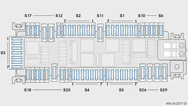
Fuse holder S1
|
Number
|
Description
|
Fuse
|
Amperes [A]
|
|---|---|---|---|
|
1
|
Additional air heating system
|
F28
|
5 A.
|
|
2
|
The main radio control unit
|
F29
|
25 A.
|
|
Preparation for mounting the radio
|
15 A.
|
||
|
3
|
Lane assistant, steering wheel
|
F30
|
10 A.
|
|
4
|
TEMPMATIC heating / air conditioning / THERMOTRONIC automatic air conditioning
|
F31
|
10 A.
|
|
5
|
Control panel with touchpad in the center of the center console
|
F32
|
7.5 amps
|
|
6
|
Radio main control unit (Vito)
|
F33
|
5 A.
|
|
Radio main control unit (Class V)
|
15 A.
|
||
|
7
|
Lighter
|
F34
|
15 A.
|
Fuse holder S2
|
Number
|
Description
|
Fuse
|
Amperes [A]
|
|---|---|---|---|
|
1
|
Driver seat control module
|
F36
|
7.5 amps
|
|
2
|
Engine compartment fuse box (PDC-E)
|
F37
|
30 A.
|
|
3
|
Airbag control module
|
F38
|
7.5 amps
|
|
4
|
DAB / SDARS digital radio / TV tuner
|
F39
|
5 A.
|
|
5
|
unassigned
|
F40
|
–
|
|
6
|
unassigned
|
F41
|
–
|
|
7
|
Passenger seat control module
|
F42
|
7.5 amps
|
Fuse holder S3
|
Number
|
Description
|
Fuse
|
Amperes [A]
|
|---|---|---|---|
|
1
|
Steering column cover module
|
F49
|
5 A.
|
|
2
|
Main radio control unit, display and fan
|
F50
|
7.5 amps
|
|
3
|
Phone holder
|
F51
|
5 A.
|
|
4
|
Media Interface
|
F52
|
5 A.
|
|
5
|
Road Toll System (DSRC), Japanese market
|
F53
|
7.5 amps
|
|
6
|
Air conditioning blower
|
F54
|
30 A.
|
|
7
|
Ignition switch / electronic steering lock
|
F55
|
20 A.
|
Fuse holder S4
|
Number
|
Receiver
|
Fuse
|
Amperes [A]
|
|---|---|---|---|
|
1
|
Front left door control module
|
F64
|
30 A.
|
|
2
|
Front right door control module
|
F65
|
30 A.
|
|
3
|
Wiper, tailgate, right-hand side (Vito)
|
F66
|
20 A.
|
|
4
|
Electric parking brake (EFS)
|
F67
|
7.5 amps
|
|
5
|
Airbag control module
|
F68
|
7.5 amps
|
|
6
|
Automatic deactivation of the passenger airbag
|
F69
|
5 A.
|
|
7
|
unassigned
|
F70
|
–
|
Fuse holder S5
|
Number
|
Description
|
Fuse
|
Amperes [A]
|
|---|---|---|---|
|
1
|
unassigned
|
F71
|
–
|
|
2
|
12 V sockets in the cargo area
|
F72
|
15 A.
|
|
3
|
Electric parking brake (EFS)
|
F73
|
30 A.
|
|
4
|
Left side electric sliding door
|
F74
|
30 A.
|
|
5
|
1 trailer module
|
F75
|
15 A.
|
|
6
|
2 trailer module
|
F76
|
25 A.
|
|
7
|
Trailer module 3
|
F77
|
25 A.
|
Fuse holders S6 to S29
|
Number
|
Description
|
Fuse
|
Amperes [A]
|
|---|---|---|---|
|
S6
|
unassigned
|
F23
|
–
|
|
S7
|
Trailer control module
|
F24
|
7.5 amps
|
|
S8
|
Additional battery, charging connector
|
F25
|
10 A.
|
|
S9
|
Trailer control module
|
F26
|
15 A.
|
|
S10
|
Fuse box in passenger footwell at the A-pillar (PDC-F)
|
F27
|
5 A.
|
|
S11
|
Rear window heating
|
F35
|
30 A.
|
|
S12
|
Rear multimedia system
|
F43
|
10 A.
|
|
S13
|
Adjusting the seat belt pretensioner on the left front seat (PRE-SAFE®)
|
F44
|
40 A.
|
|
S14
|
Adjusting the seat belt pretensioner on the right front seat (PRE-SAFE®)
|
F45
|
40 A.
|
|
S15
|
SCR exhaust gas treatment system 3
|
F46
|
10 A.
|
|
S16
|
SCR exhaust gas treatment system 2
|
F47
|
20 A.
|
|
S17
|
SCR exhaust gas treatment system 1
|
F48
|
15 A.
|
|
S18
|
Exhaust gas treatment system, SCR relay
|
F56
|
15 A.
|
|
S19
|
Additional air heating system.
|
F57
|
25 A.
|
|
S20
|
unassigned
|
F58
|
–
|
|
S21
|
Passenger seat control module
|
F59
|
30 A.
|
|
S22
|
Driver seat control module
|
F60
|
30 A.
|
|
S23
|
Amplifier, sound system
|
F61
|
40 A.
|
|
S24
|
Roof indicators
|
F62
|
10 A.
|
|
S25
|
Fuel supply control module
|
F63
|
20 A.
|
|
S26
|
Panoramic roof
|
F78
|
30 A.
|
|
S27
|
The module for reading signals and implementing CBC commands 1
|
F79
|
40 A.
|
|
S28
|
The module for reading signals and implementing CBC commands 3
|
F80
|
40 A.
|
|
S29
|
Rear air conditioning blower
|
F81
|
30 A.
|
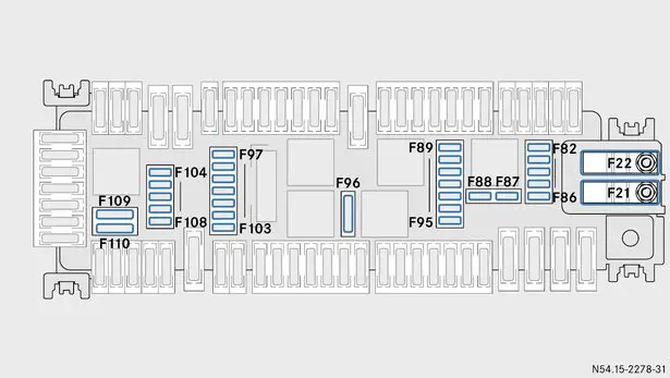
Additional fuses on the relay board
|
Number
|
Description
|
Fuse
|
Amperes [A]
|
|---|---|---|---|
|
–
|
Additional PTC heater
|
F21
|
200 A.
|
|
–
|
Additional battery
|
F22
|
200 A.
|
|
–
|
Star 2 central data bus
|
F82
|
5 A.
|
|
–
|
Ignition switch
|
F83
|
7.5 amps
|
|
–
|
Control panel in the center console / control panel on the left side of the steering wheel
|
F84
|
7.5 amps
|
|
–
|
Radio remote control receiver / COM module
|
F85
|
5 A.
|
|
–
|
RF antenna
|
F86
|
5 A.
|
|
–
|
Diagnostic connector
|
F87
|
10 A.
|
|
–
|
Instrument cluster
|
F88
|
10 A.
|
|
–
|
Light switch
|
F89
|
5 A.
|
|
–
|
Blind Spot Assistant
|
F90
|
5 A.
|
|
–
|
Aftertreatment system, SCR control module
|
F91
|
5 A.
|
|
–
|
Fuel supply control module
|
F92
|
5 A.
|
|
–
|
Preparation for mounting the radio
|
F93
|
7.5 amps
|
|
Road Toll System (DSRC), Japanese market
|
|||
|
–
|
unassigned
|
F94
|
–
|
|
–
|
Illumination of the glove box in the instrument panel
|
F95
|
5 A.
|
|
–
|
Tailgate wiper / tailgate left (Vito)
|
F96
|
15 A.
|
|
–
|
PARKTRONIC / Active Parking Assist
|
F97
|
5 A.
|
|
–
|
Signal reading and actuation module, CBC control cable
|
F98
|
5 A.
|
|
–
|
Tire pressure control
|
F99
|
5 A.
|
|
–
|
Amplifier, sound system
|
F100
|
5 A.
|
|
–
|
Control panel in the roof
|
F101
|
10 A.
|
|
–
|
unassigned
|
F102
|
–
|
|
–
|
Installation prepared for the installation of the taximeter
|
F103
|
5 A.
|
|
–
|
Rear multimedia system, left display
|
F104
|
5 A.
|
|
–
|
Rear multimedia kit, right display
|
F105
|
5 A.
|
|
–
|
Camera of driver assistance systems
|
F106
|
5 A.
|
|
–
|
Installation prepared for the installation of TV / traffic observation camera
|
F107
|
5 A.
|
|
–
|
Reversing camera / 360 ° camera
|
F108
|
7.5 amps
|
|
–
|
unassigned
|
F109
|
–
|
|
–
|
The module for reading signals and implementing CBC 5 commands
|
F110
|
30 A.
|
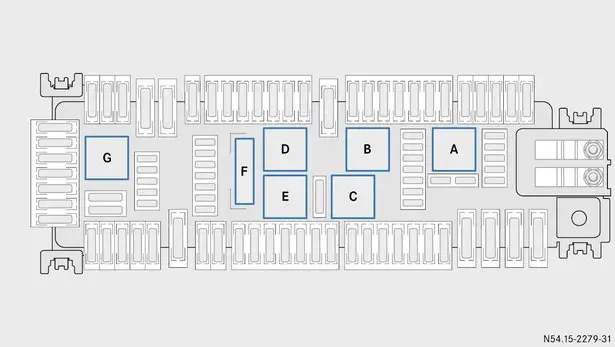
Relays
|
Number
|
Description
|
Relay
|
|---|---|---|
|
–
|
Terminal 15 relay
|
A
|
|
–
|
Rear window wiper
|
B
|
|
–
|
Terminal 15 R2
|
C.
|
|
–
|
Rear window heating
|
D
|
|
–
|
Terminal 15 R1
|
E.
|
|
–
|
Terminal 30 G
|
F.
|
|
–
|
Exhaust gas treatment system, SCR pressure pump
|
G.
|
Fuse box in the passenger footwell at the A-pillar

- Opening: Open the passenger door.
- Open the cover 1 in the direction of the arrow and remove it.
- You can see the fuse box at the A pillar.
- Closing: Insert cover 1 on the left into the side trim and close.
- Close the passenger door.
Fuses

Fuse holder S1
|
Number
|
Description
|
Fuse
|
Amperes [A]
|
|---|---|---|---|
|
1
|
Rear seat heating / ventilation, 1st row, left-hand side
|
F305
|
10 A.
|
|
2
|
Seat heating / ventilation, 1st row, right
|
F308
|
10 A.
|
|
3
|
Rear seat heating / ventilation, 2nd row, left
|
F310
|
10 A.
|
|
4
|
Seat heating / ventilation, 2nd row, right
|
F309
|
10 A.
|
|
5
|
unassigned
|
F316
|
–
|
|
6
|
Seat heating / ventilation control module
|
F317
|
5 A.
|
Fuse holder S2
|
Number
|
Description
|
Fuse
|
Amperes [A]
|
|---|---|---|---|
|
1
|
Parameterizable special module (PSM)
|
F303
|
25 A.
|
|
2
|
Parameterizable special module (PSM)
|
F304
|
25 A.
|
|
3
|
Refrigerator in the center console
|
F306
|
10 A.
|
|
4
|
Voltage converter
|
F312
|
30 A.
|
|
5
|
Right-hand electric sliding door / EASY-PACK tailgate
|
F311
|
30 A.
|
|
6
|
unassigned
|
F318
|
–
|
Fuse holders S3 to S6
|
Number
|
Description
|
Fuse
|
Amperes [A]
|
|---|---|---|---|
|
S3
|
MARCO POLO charger, charging connector
|
F300
|
25 A.
|
|
S4
|
Terminal 30, body builder
|
F321
|
25 A.
|
|
Cup holder in the center console
|
10 A.
|
||
|
S5
|
unassigned
|
F302
|
–
|
|
S6
|
Additional air heating system
|
F323
|
25 A.
|
Fuse holder S10
|
Number
|
Description
|
Fuse
|
Amperes [A]
|
|---|---|---|---|
|
1
|
Tachograph
|
F301
|
5 A.
|
|
2
|
unassigned
|
F307
|
–
|
|
3
|
Tachograph
|
F315
|
7.5 amps
|
|
5
|
The key in the ignition switch is in position 2
Switch-on signal: refrigerator, cup holder, center console pickup
|
F314
|
5 A.
|
|
6
|
Terminal 61, body builder
|
F319
|
15 A.
|
|
Only for bodybuilder Westfalia
|
5 A.
|
||
|
7
|
Terminal 15, body builder
|
F320
|
15 A.
|
|
Only for bodybuilder Westfalia
|
5 A.
|
||
|
8
|
Additional air heating system
|
F322
|
5 A.
|
Relays
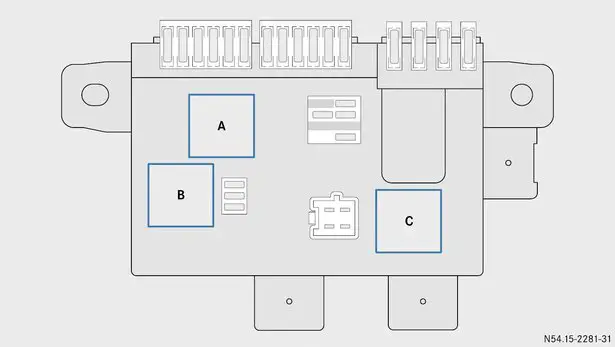
90 ° inverted view
|
Number
|
Description
|
Relay
|
|---|---|---|
|
–
|
Terminal 15 relay
|
A
|
|
–
|
unassigned
|
B
|
|
–
|
unassigned
|
C.
|
Rear fuse box
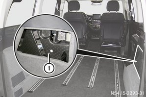
- Opening: Open the tailgate.
- Remove the tool kit from the storage compartment at the rear (see vehicle owner’s manual).
- Remove tool cup 1 from the side trim.
- 3 fuse holders and a relay socket are shown.
- Closing: Insert the tool cup 2 in the storage compartment at the rear and lock it.
- Stow tools, replace storage compartment cover and click into place (see vehicle owner’s manual).
- Close the tailgate.
Fuses and relays
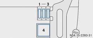
Fuse and relay socket behind the tool socket.
Fuses
|
Number
|
Description
|
Fuse
|
Amperes [A]
|
|---|---|---|---|
|
1
|
12-volt socket on the 1st row of seats, left-hand side
|
F352
|
15 A.
|
|
2
|
12-volt socket on the 2nd row of seats, left-hand side
|
F350
|
15 A.
|
|
3
|
12-volt socket on the 2nd row of seats, right-hand side
|
F351
|
15 A.
|
Relay
|
Number
|
Description
|
Relay
|
|---|---|---|
|
4
|
12 V sockets on the rear
|
K127
|
Pre-fuse holder
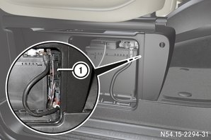
Open battery compartment in right-hand front seat box
The pre-fuse holder 1 is located next to the starter battery in the box of the right front seat.
Always have the fuses replaced in pre-fuse holder 1 by a qualified service center.
Fuses A3, A7, A10, A 11, A13 and A16 are on the bottom.
|
Number
|
Description
|
Fuse
|
Amperes [A]
|
|---|---|---|---|
|
1
|
unassigned
|
A16
|
–
|
|
2
|
unassigned
|
A15
|
–
|
|
3
|
Starter
|
A1
|
Pyrotechnic fuse
|
|
4
|
Fuse box in passenger footwell at the A-pillar (PDC-F)
|
A8
|
150 A.
|
|
5
|
Additional battery
|
A12
|
150 A.
|
|
6
|
Glow plug control module
|
A2
|
100 A.
|
|
7
|
Alternator
|
E2
|
350 A.
|
|
8
|
Engine radiator fan
|
A10
|
100 A.
|
|
9
|
unassigned
|
A9
|
–
|
|
10
|
Engine compartment fuse box (PDC-E)
|
A7
|
150 A.
|
|
11
|
unassigned
|
A14
|
–
|
|
12
|
unassigned
|
A3
|
–
|
|
13
|
Fuse box in passenger footwell (PDC-P)
|
A6
|
250 A.
|
|
14
|
The module for reading signals and implementing CBC commands
|
A13
|
40 A.
|
|
15
|
unassigned
|
A5
|
–
|
|
16
|
Electric power steering
|
A11
|
100 A.
|
|
17
|
Rear sockets
|
A4
|
50 A.
|