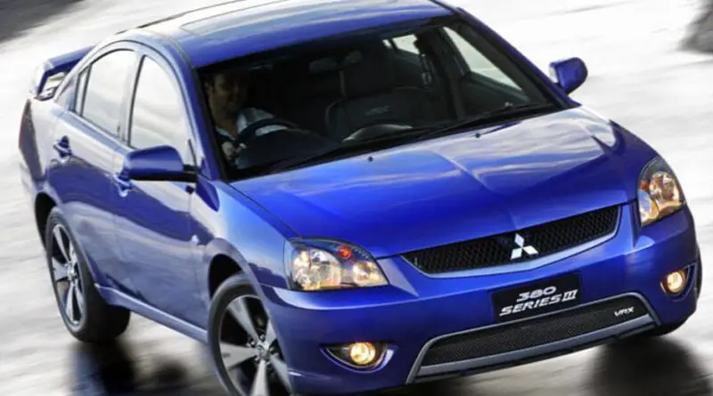
Mitsubishi 380 (2005-2008) – fuse and relay box
Diagrams of fuse and relay boxes – Mitsubishi 380, 380LS, 380LX, 380VRX, 380GT
Applies to vehicles manufactured in the years:
2005, 2006, 2007, 2008.
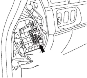
Instrument panel fuse box
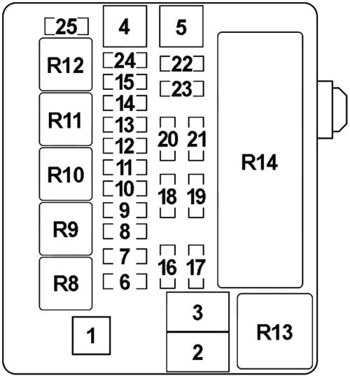
The scheme of the fuse box
| Number | Amperes [A] | Description |
|---|---|---|
| 1 | thirty | Rear window defogger |
| 2 | thirty | Blower motor and resistor |
| 3 | – | – |
| 4 | – | – |
| 5 | 15 | Accessory socket |
| 6 | 15 | Data link connector, ETACS-EC |
| 7 | 15 | ETACS-ECU |
| 8 | – | – |
| 9 | 7.5 | Mounting the sunroof |
| 10 | 7.5 | Remote controlled mirror |
| 11 | – | – |
| 12 | – | – |
| 13 | 7.5 | Fuel pump relay, engine ECU |
| 14 | twenty | Wipers |
| 15 | 7.5 | Remote controlled mirror |
| 16 | 7.5 | A / C compressor clutch relay, A / C-ECU, blower relay, condenser fan motor, fan control relay, front ECU, outside / inside air damper control motor, rear window defogger relay |
| 17 | – | – |
| 18 | 7.5 | A / T control relay, input shaft speed sensor, output shaft speed sensor, engine ECU, rear combination lamp, SRS-ECU |
| 19 | 7.5 | ABS-ECU, ABS / TCL-ECU, Column switch, Combined counter, ETACS-ECU, Multi-center display, SRS-ECU |
| 20 | 10 | The ignition coil |
| 21 | – | – |
| 22 | – | – |
| 23 | 10 | Mounting the sunroof |
| 24 | – | – |
| R1 | – | |
| R2 | – | |
| R3 | Fuel pump №2 | |
| R4 | Accessory socket | |
| R5 | Fuel pump №1 | |
| R6 | Power windows | |
| R7 | Blower | |
| R8 | Rear window defogger | |
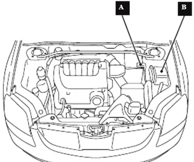
Fuse boxes in the engine compartment
A – fuse box;
B – Fusible link (positive battery terminal).
The scheme of the fuse box
| Number | Amperes [A] | Description |
|---|---|---|
| 1 | 60 | Fuse (passenger compartment): “5”, “6”, “9”, “10” |
| 2 | 50 | Radiator fan motor |
| 3 | thirty | ABS-ECU and ABS / TCL-ECU (engine power) |
| 4 | 40 | Ignition switch |
| 5 | 40 | Windshield lifter motor, seat assembly, main window switch, rear window motor, fuse (passenger compartment): “3”, “4” |
| 6 | 15 | Fog lamp and fog lamp relay |
| 7 | twenty | – |
| 8 | 15 | Horn (high), horn (low) and horn relay |
| 9 | twenty | Camshaft Position Sensor, Crankshaft Position Sensor, Engine Oil Control Valve, Vapor Purge Solenoid, Vapor Purge Solenoid, Heated Oxygen Sensor, ETACS-ECU, Injector, Mass Air Flow Sensor, MPI Relay, Engine ECU, A / T ECU, Actuator Throttle Control Motor Relay, Fan Control Relay |
| 10 | 10 | A / C Compressor Assembly, A / C-ECU |
| 11 | 15 | ABS-ECU, ABS / TCL-ECU, High Mount Stop Lamp, Engine ECU, Rear Combination Lamp |
| 12 | – | – |
| 13 | 7.5 | Alternator |
| 14 | 10 | ETACS-ECU, Beacons |
| 15 | twenty | A / T Transmission Control Solenoid Valve, Engine ECU |
| 16 | 15 | Right headlight (high beam) |
| 17 | 15 | Left headlight (high beam) |
| 18 | 10 | Right headlight (low beam) |
| 19 | 10 | Left headlight (low beam) |
| 20 | 7.5 | A / C-ECU, A / T Lever Position Light, Combination Meter, Fog Lamp Switch, Headlight (RH), Glove Box Lamp, Hazard Light Switch, Multi-Center Display, Radio, CD Player, Rear Combination Lamp (RH) , Rheostat, TCL switch |
| 21 | 7.5 | Headlamp (LH), License plate lamp, Rear combination lamp (LH) |
| 22 | 15 | A / C-ECU, Column Switch, Combined Meter, ETACS-ECU, Front ECU, Key Reminder Switch, Multi-Center Display, Radio, CD Player, Cosmetic Mirror Lamp |
| 23 | 10 | A / C-ECU, Accessory Socket Relay, ETACS-ECU, Multipoint Display, Radio, CD Player |
| 24 | 15 | Fuel pump module |
| 25 | thirty | Front ECU, Windshield Wiper Motor |
| 27 | 120 | Positive battery terminal: battery, starting system, front ECU, fuse (engine compartment main box) No: “1”, “2”, “3”, “4”, “5”, “6”, “7”, ” 8 “,” 9 “,” 10 “,” 11 “,” 12 “,” 13 “,” 14 “,” 15 “,” 22 “,” 24 “,” 26 “ |
| R8 | Fog light | |
| R9 | Horn | |
| R10 | – | |
| R11 | – | |
| R12 | – | |
| R13 | Fan control | |
| R14 | Front-ECU | |
Relay box
| Number | Relay |
|---|---|
| R10 | – |
| R11 | – |
| R12 | – |
| R13 | – |
| R14 | A / T control |
| R15 | MPI control |
| R16 | Air conditioning compressor clutch |
ABS fuse link
| Number | Amperes [A] | Description |
|---|---|---|
| 26 | twenty | Anti-lock braking system (solenoid valve) |


