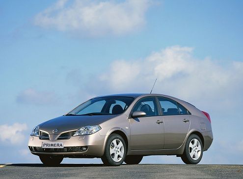
Nissan Primera P12 (2001-2007) – fuse and relay box
Diagrams of fuse and relay boxes – Nissan Primera P12
Applies to vehicles manufactured in the years:
2001, 2002, 2003, 2004, 2005, 2006 and 2007.
Passenger compartment
It is located in the dashboard behind a protective cover.
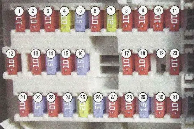
Description
| 1 – 10A | Public address system |
| 2 – 10A | Cruise control |
| 3 – 10A | Electric drive for the boot lock |
| 4 – 20A | Electric socket in the luggage compartment |
| 5 – 15A | Stop lights |
| 6-10A | Fog lights |
| 7-20A | Heated rear window (tailgate glass) |
| 8-10A | Heated front seats |
| 9-10A | Cruise control |
| 10 – 10A | Power supply for electronic devices |
| 11 – 10A | Automatic transmission control system |
| 12 – 10A | Power supply for electronic devices |
| 13 – 10A | Indoor lampshades |
| 14 – 15A | Blower motor |
| 15 – 10A | Air conditioning |
| 16 – 15A | Blower motor |
| 17 – 10A | Engine management system |
| 18 – 10A | Supplemental Secure System (SRS) |
| 19 | Reserve |
| 20 – 10A | Engine management system |
| 21 – 10A | Starter solenoid relay |
| 22 – 15A | Lighter |
| 23 – 10A | Electric actuators for outside rear view mirrors |
| 24 – 15A | Electric socket in the center console |
| 25 – 20A | Windshield wiper |
| 26 – 15A | Windscreen and tailgate washers |
| 27 – 10A | Sensors |
| 28 – 10A | Tailgate window cleaner |
| 29 – 15A | Fuel pump |
| 30 – 10A | Instrument cluster |
| 31 – 10A | Anti-lock brake system (ABS) |
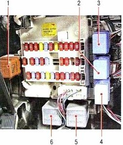
Relay on front of fuse box panel
Description
- rear window heater relay;
- throttle motor relay;
- fog lamp relay;
- window regulator relay;
- relay switches;
- relay switches.
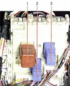
Relay on rear panel of fuse box
Description
- ignition relay;
- auxiliary equipment relay;
- air blower relay for ventilation, heating and air conditioning
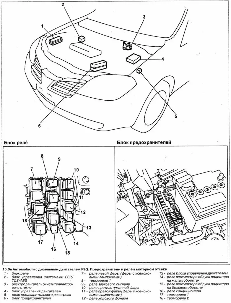
Engine compartment
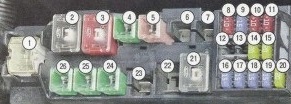
Fuse mounting box
Description
| 1 – 120A | First main fuse |
| 2 – 80A | Ignition on consumers |
| 3 – 50A | Anti-lock braking system pump motor |
| 4 – 40A | Ignition switch (lockout) |
| 5 – 30A | Anti-lock braking system solenoid valves |
| 6 | Reserve |
| 7 | Reserve |
| 8-10A | parking lights |
| 9 – 15A | Public address system |
| 10 – 10A | Engine management system |
| 11 – 15A | Sound signal |
| 12 | Reserve |
| 13 | Reserve |
| 14 – 15A | Low beam (left headlight) |
| 15 – 15A | Low beam (right headlight) |
| 16 – 15A | Throttle actuator motor |
| 17 – 15A | High beam (left headlight) |
| 18 – 15A | High beam (right headlight) |
| 19 – 15A | Fog lights |
| 20 – 20A | Ignition coils |
| 21 – 80A | Second main fuse |
| 22 | Reserve |
| 23 – 30A | Headlight washers |
| 24 – 40A | Second radiator fan motor |
| 25 – 40A | 1.cooler fan motor |
| 26 – 40A | Electric windows |
Relay box
Type 1
Description
- fog lamp relay;
- radiator fan relay;
- auxiliary equipment relay;
- radiator fan relay;
- A / C compressor electromagnetic clutch relay;
- radiator fan relay;
- relay for engaging automatic transmission or variator modes “P” (parking) “N” (neutral);
- a relay for turning on the dipped beam during the day;
- sound signal relay;
- radiator fan relay.

