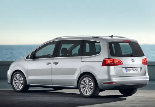
Volkswagen Sharan (7N1) (2010-2015) – fuse box
Volkswagen Sharan (7N1) – fuse box diagram
Year of production: 2010, 2011, 2012, 2013, 2014, 2015.
The cigarette lighter fuse (power socket) on the Volkswagen Sharan (7N1) is a 15A (front) and 31 (rear) 15A fuse in the fuse box in the passenger compartment.
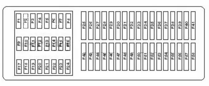
In the passenger compartment
The box is on the driver’s side.
| Number | Description | Amperes [A] |
| F4 | Starter relay | 10 |
| F5 | Suspension control system | 10 |
| F9 | SRS | 7.5 |
| F10 | Equipment for special vehicles | 5 |
| F11 | 4WD control system | 10 |
| F12 | Xenon headlight (left) | 10 |
| F13 | 5 | |
| F14 | 7.5 | |
| F15 | 10 | |
| F 16 | Xenon headlight (right) | 10 |
| F17 | Telephone | 5 |
| F18 | Equipment for special vehicles | 7.5 |
| F20 | ABS / ESP | 5 |
| F21 | Air conditioner;
Heating. |
5 |
| F24 | Remote control system for central locking and engine start | 7.5 |
| F26 | Air conditioner;
Heating. |
5 |
| F28 | Rear window wiper motor | 10/15 |
| F36 | Parking brake | 30 |
| F37 | 10/25 | |
| F38 | 10/30 | |
| F39 | Steering column electronics control unit | 7.5 |
| F40 | Multimedia system | 5 |
| F41 | Instrument cluster | 5 |
| F42 | Suspension control system | 15 |
| F43 | Electric seat | 30 |
| F44 | 25 | |
| F45 | 30 | |
| F46 | 30 | |
| F47 | 10 | |
| F48 | 15 | |
| F49 | Parking brake | 30 |
| F50 | 30 | |
| F51 | Seat heating | 30 |
| F52 | 20/30 | |
| F53 | Accessory power connector | 30 |
| F54 | Steering column lock | 10 |
| F55 | Trailer electrical connector | 25 |
| F56 | Trailer control unit | 30 |
| F57 | Two-channel radio | 10 |
| F58 | Equipment for special vehicles | 25 |
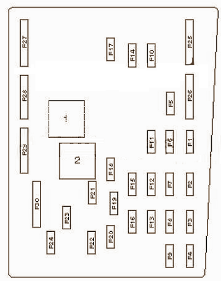
In the engine compartment
Main box diagram
| Number | Description | Amperes [A] |
| F1 | Voltage stabilizer block | 30 |
| F2 | On-board supply control unit | 30 |
| F3 | ABS / ESP | 30 |
| F4 | On-board power control unit;
Power circuit; Left lighting. |
30 |
| F5 | Battery control unit | 5 |
| F6 | Power circuit;
Lighting on the right. |
30 |
| F7 | Two-tone horn relay;
Heated windshield relay. |
25 |
| F8 | Sound amplifier | 30 |
| F9 | Audio system;
Navigation. |
20 |
| F10 | Engine management | 30 |
| F11 | Diagnostic unit | 5 |
| F12 | Mechatronic unit DSG | 15 |
| F13 | Main Relay | 5 |
| F14 | Engine management | 10/30 |
| F15 | – | |
| F 16 | Engine management | 15/30 |
| F17 | 15/20 | |
| F18 | Fuel pump | 30 |
| F19 | Windshield wiper | 30 |
| F20 | Auxiliary coolant pump relay | 15 |
| F21 | Additional heater | 20 |
| F22 | Headlight cleaning relay | 20/30 |
| F23 | 15 | |
| F24 | 10 | |
| F25 | ABS / ESP system | 40 |
| F26 | Supply fan control unit | 40 |
| F27 | Main ignition circuits | 50 |
| F28 | Glow plugs | 50 |
| F29 | 40 | |
| F30 | Auxiliary circuits | 50 |
Power box diagram
| Number | Description | Amperes [A] |
| 1 | Charging system;
Generator. |
150/200 |
| 2 | Power steering | 80 |
| 3 | Cooling fan motor control unit | 80 |
| 4 | 80 | |
| 5 | 100 | |
| 6 | Heated windscreen | 50 |
| 7 | Coolant heater | 70 |
| 8 | Thermal fuse 2. Right rear sliding door. Thermal fuse 1. Adjust the position of the driver’s seat. Thermal fuse 1. Adjust the position of the front passenger seat |
60 |
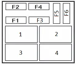
In the trunk
| Number | Description | Amperes [A] |
| F1 | Left electric sliding door | 40 |
| F2 | Rear door opening / closing drive controller | 30 |
| F3 | Trailer control unit | 30 |
| F4 | 30 | |
| 1 | Trailer connector feed relay |


