

Volkswagen Touran (1T) (2003-2015) – fuse box
Volkswagen Touran (1T) – fuse box diagram
Year of production: 2003, 2004, 2005, 2006, 2007, 2008, 2009, 2010, 2011, 2012, 2013, 2014, 2015.
The cigarette lighter (power socket) fuse on the Volkswagen Touran 1T is fuse 30, 42 and 47 in the instrument panel fuse box.
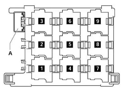
Passenger compartment
Locations
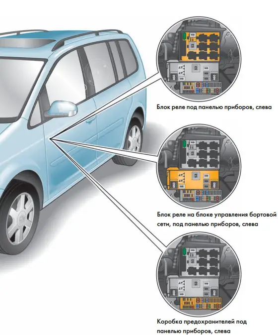
All the main boxes are located under the dashboard, on the driver’s side, behind the glove box.
Structure
Fuse box
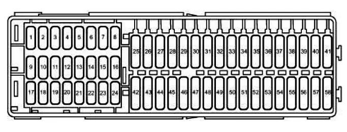
Description
| 1 | 5 / 10A Electrochromic interior rearview mirror;
On-board supply control unit. |
| 2 | 5 / 10A Trailer connector;
Data bus diagnostic interface; Fuel pump relay; Engine control unit; Power relay, class thirty |
| 3 | 5A Headlight cleaning relay;
Headlamp range adjustment control unit; Power steering control unit; Trailer detection control unit; Adaptive lighting and headlight range adjustment control unit; Trailer detection control unit; Stop light switch; 2 ESP and ASR indicator light; Adjusting the tilt angle button of the rear left seat cushion; ASR switch; Tire pressure indicator button; Mechatronics for DSG gearbox; Automatic gearbox control unit; ABS controller; Button for deactivating ASR and ESP. |
| 4 | 10A Fuel pump controller;
Garage door opener. |
| 5 | 5A Heated front seats;
Air flow meter; Heating resistor for crankcase ventilation; Warning buzzer for training car; Control unit for controlling the electronics of the mobile phone. |
| 6 | 5A Airbag control unit;
Passenger’s front airbag deactivation warning lamp. |
| 7 | 5A Heated front seat heating air conditioner |
| 8 | 5A Heated windshield washer nozzles |
| 9 | 5A Airbag;
10A Onboard supply control unit; Adaptive lighting and headlight range control unit. |
| 10 | 5A Telephone;
Data bus diagnostic interface. |
| 11 | 10A Power steering;
Parking assist control unit. |
| 12 | 5 / 10A Automatic gearbox;
Fuel pump control unit; Left headlight range control actuator; Headlamp range control unit; Trailer recognition control unit. |
| 13 | 10A headlight range control |
| 14 | 5 / 10A Anti-lock brake system (ABS);
Motor 2 driver; Crankcase ventilation heating resistor; Fuel pump controller. |
| 15 | 5A diagnostic (DLC) connector;
Reversing lamps; Airbag controller; Taxi; Mirror taximeter; Tiptronic switch. |
| 16 | 5A Data bus connector;
Instrument cluster control unit; Fresh air blower switch; Heating and operating mode switch; High pressure sensor; Driver seat heating control unit; Fast heating button; Parking assist button. |
| 17 | 7,5А Special cars |
| 18 | 5A Emergency data recorder;
Anti-theft system remote control module. |
| 19 | 5A Luggage compartment lighting, left;
Taximeter. |
| twenty | 10A Parking system control unit;
Automatic gearbox control unit; ABS control unit. |
| 21 | 5 / 10A Radio signal receiver for additional water heater;
Multi-function switch; On-board power controller; Automatic gearbox control unit; Gear lever position sensor controller; Multi-function switch. |
| 22 | 7.5 A Auxiliary heater;
Multimedia system control unit. |
| 23 | 10A Brake lights;
Voltage monitoring relay. |
| 24 | 10A Auxiliary heater;
Diagnostic Connector (DLC); Heating; Air conditioning; Light switch. |
| 25 | 20A Brake vacuum pump;
Automatic gearbox control unit. |
| 26 | 10A Engine management (injectors, ignition coils) |
| 27 | 20A Automatic gearbox control unit |
| 28 | 5A Light switch;
Rain and light sensor; Climatronic control unit. |
| 29 | 15A Rear window wiper motor;
Windscreen and rear window washer pump. |
| thirty | 20A Reflector socket;
Rear cigarette lighter; Blocking diode. |
| 31 | 15A Auxiliary heater |
| 32 | Windshield washer 15A |
| 33 | 10A Service vehicles;
40A Heater and operation mode selection switch; Fresh air blower relay; Air conditioning control unit. |
| 34 | |
| 35 | 10A / 40A heating air conditioner |
| 36 | 10A service vehicles |
| 37 | – |
| 38 | – |
| 39 | – |
| 40 | 20A trailer electrical connector |
| 41 | 20A Trailer electrical connector or TSU socket (cigarette lighter) |
| 42 | 15A accessory power connector (cigarette lighter) |
| 43 | 15A Fuel pump control unit |
| 44 | 5A Anti-theft system;
40A Supply fan control unit. |
| 45 | 20A audio system;
Sliding sunroof control unit. |
| 46 | 5A Multifunction control unit 1 |
| 47 | (25A) Cigarette lighter fuse or front seat control unit |
| 48 | 20A Headlight washer system;
Front seat control unit. |
| 49 | 10A Door controller (driver);
Door control (passenger). |
| 50 | 30A Heated front seats;
Central control unit of the Convenience system. |
| 51 | 20A tailgate |
| 52 | 25A Multifunction control unit 1;
Auxiliary heater. |
| 53 | 25A Multifunction control module 2;
Headlight cleaning relay. |
| 54 | 5A automatic gearbox |
| 55 | 5A service vehicles |
| 56 | 15A / 40A heating air conditioner |
| 57 | 30A Door switchboard (driver);
Door control unit (passenger). |
| 58 | 30A ECM door (rear left);
ECM door (rear right). |
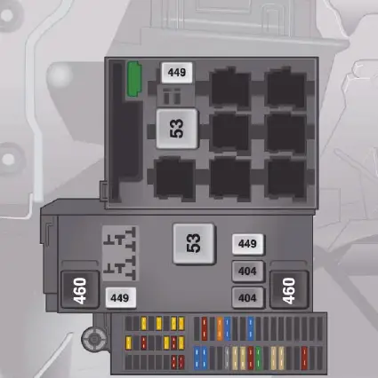
Relay box
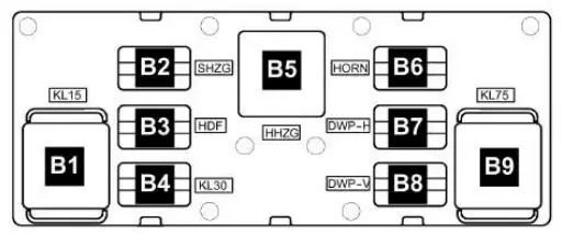
Description
- B1 – J681 – terminal 15 power relay 2 (460)
- B2 – J99 – Heated exterior mirror relay (449)
- ВЗ – not used
- B4 J689 Terminal 30 power relay 2 (449)
- B5 – J9 – rear window heating relay (53)
- B6 – J 4 – Two-tone horn relay (449)
- B6 – J 413 – Horn relay (449)
- B7 – J729 – Relay 1 double washer pump (404)
- B8 – J 730 – relay 2 double washer pump (404)
- B9 – J 59 – Relay relief contact X (460)
Body relay box
Description
- J496 – Auxiliary coolant pump relay (449)
- J39 – Headlight cleaning system relay (53)
- 1) J17 Fuel pump relay (449) 2) J643 Fuel injection relay (449)
- J13 – Supply fan relay (404)
- J3ЗЗ – Fuel pump shutdown relay (404)
- unused
- J485 – Relay for auxiliary heater operation (449)
- J682 – Terminal 50 power supply relay (433), from May 2006 (53)
- unused
A – Thermal fuse 1 for driver seat adjustment – 30A. J17 and J643 are mini relays and are installed (depending on equipment) in a single slot in the relay block.
Engine compartment
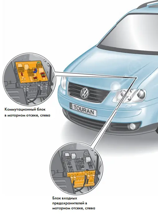
Fuse and relay box
This communication box is located on the left side of the engine compartment, next to the battery.
Type 1
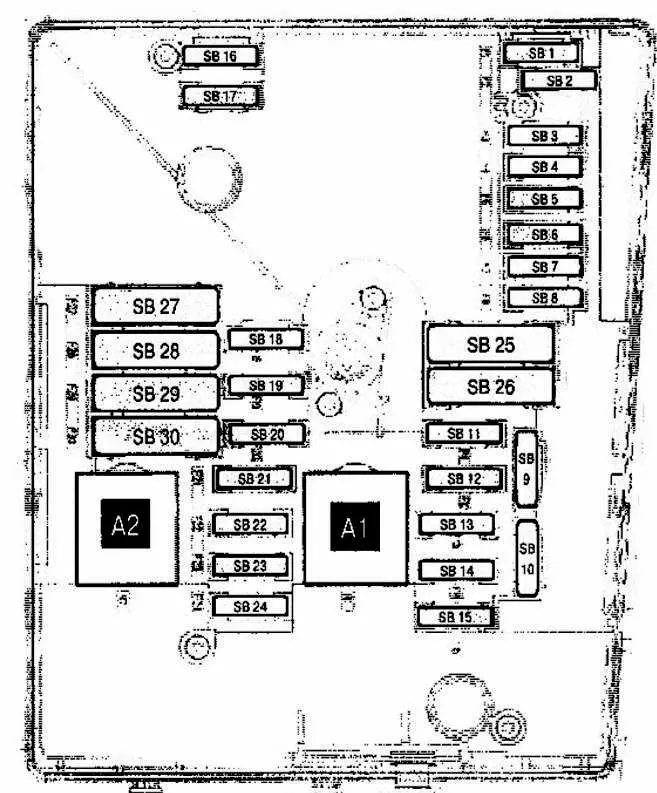
Description
| A1 | (100/458) Ignition main circuit relay |
| A2 | (100) Exhaust air pump relay (BSX) |
| 1 | (20A / 25A / 30A) Windshield wiper motor 2 (dual wiper motor system) |
| 2 | (5A) Steering column control module |
| 3 | (5A) Multifunction control module 1 |
| 4 | (30A) Anti-lock brake system (ABS) |
| 5 | (15A) Gearbox control system (automatic gearbox) (manual gearbox (DSG) |
| 6 | (5A) Instrument cluster control module |
| 7 | – |
| 8 | (15A) Audio system;
Navigation system. |
| 9 | (5A) Telephone |
| 10 | (5A / 10A) Engine management |
| 11 | (20A) Auxiliary heater |
| 12 | (5A) Diagnostic unit |
| 13 | (25A / 30A) Engine management |
| 14 | (20A) Engine management |
| 15 | (5A / 15A) Engine management |
| 16 | (30A) Anti-lock brake system (ABS) |
| 17 | (15A) Horn;Multifunction control module 1. |
| 18 | (30A) Audio system (some models), special vehicle |
| 19 | (30A) Windshield wiper motor 1 |
| twenty | (40A) Glow plug control module |
| 21 | (10A / 15A) Engine management |
| 22 | (5A) Brake light switch (brake pedal position sensor);
Clutch pedal position sensor. |
| 23 | (5A / 10A / 15A) Engine management |
| 24 | (10A) Cooling fan motor control module;
Coolant pump relay (some models); Thermostat; Engine management. |
| 25 | (40A) Multifunction control module 1 |
| 26 | (40A) Multifunction control module 1 |
| 27 | (40A / 50A) Glow plug control module;
Exhaust air pump motor. |
| 28 | (40A) Multifunction control module 1;
Multifunction control module 2. |
| 29 | (50A) Coolant pump relay (some models) |
| thirty | (40A) Instrument cluster 1 fuse / relay box (F7 / F8 / F28-F35);
Auxiliary ignition circuits relay. |
Type 2
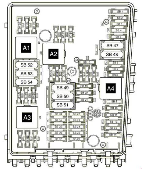
Description
| A1 | Relay 2 main ignition circuits |
| A2 | Starter relay |
| A3 | Fuel pump relay – 1.6 (BGU) |
| A4 | Relay 1 of the main ignition circuits |
| 1 | 30A Anti-lock brake system (ABS) |
| 2 | 30A Anti-lock brake system (ABS) |
| 3 | 25A windshield wiper |
| 4 | 5A Multifunction control unit 1 |
| 5 | 20A Multifunction control unit 1, signal |
| 6 | 15A / 20A Engine control system, ignition coil – petrol |
| 7 | 5A engine management, clutch pedal position sensor |
| 8 | 10A Cooling blower motor, EGR valve |
| 9 | 10A Engine management;
Fuel pump relay; Glow plug control unit. |
| 10 | 5A / 10A engine management;
Secondary air pump relay; Lambda probe. |
| 11 | 25A / 30A engine management |
| 12 | 15/25 / 30A Engine management;
Motronic control unit; Injection system control unit. |
| 13 | Automatic gearbox 15A |
| 14 | |
| 15 | 40A Starter |
| 16 | 15A Steering column control module |
| 17 | 10A Instrument cluster |
| 18 | 30A Audio system |
| 19 | 15A Audio system |
| twenty | Telephone 10A |
| 21 | |
| 22 | |
| 23 | |
| 24 | 10A data bus connector |
| 25 | |
| 26 | 10A Engine management system – except 1.6 (BGU);
Motronic control unit. |
| 27 | 10A Crankcase ventilation heater |
| 28 | Automatic gearbox 20A |
| 29 | Engine management 10 / 20A – 1.6FSi (BAG) / 2.0FSi (AXW);
Ignition coils. |
| thirty | Auxiliary heater 20A |
| 31 | 25A windshield wiper |
| 32 | 10A Engine management;
Cylinder injectors. |
| 33 | 15A booster fuel pump |
| 34 | – |
| 35 | – |
| 36 | – |
| 37 | – |
| 38 | 10A Headlight range control |
| 39 | 5A Engine oil temperature sensor;
Instrument cluster. |
| 40 | 20A Instrument panel relay fuse box 1 |
| 41 | – |
| 42 | 5A Engine management;
Air mass meter; Power relay for engine electronics. |
| 43 | 20A brake assist vacuum pump |
| 44 | – |
| 45 | 15A Heated lambda probe;
Lambda probe. |
| 46 | – |
| 47 | 40A Multifunction control module 1 |
| 48 | 40A Multifunction control module 1 |
| 49 | 50A Relay 1 main ignition circuits |
| 50 | – |
| 51 | 40A glow plug control unit |
| 52 | 50A Multifunction control unit (On-board power control unit) |
| 53 | 50A Door Controls, Instrument Panel Fuse / Relay Box |
| 54 | 50A Radiator fan control unit |
Input fuse box
High-power fluxes.
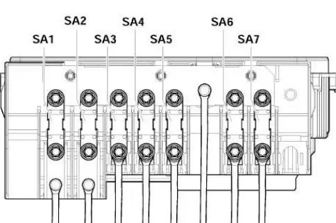
Description
| 1 | (150A / 200A) Generator |
| 2 | (80A) Power steering |
| 3 | (80A) Cooling fan motor |
| 4 | (80A) Service vehicles |
| 5 | (100A) (for vehicles manufactured after October 2005) – additional heater |
| 6 | (80A / 100A) Distribution board fuse / Relay box 1 (F20-F24 / F42-F56);
40A Low heat output relay. |
| 7 | (50A) Dashboard fuse / relay box 1 (F39 / F41) (for vehicles manufactured before April 2006) – trailer electrics |
Additionally, a glow plug control and protection relay can be installed at the bottom of this unit on a diesel model.