

BMW 5 E39 (1996-2003) – fuse and relay box
Diagrams of fuse and relay boxes – BMW 5 E39
Applies to vehicles manufactured in the years:
1996, 1997, 1998, 1999, 2000, 2001, 2002, 2003.
The cigarette lighter in the BMW 5 E39 is fuse number F7 (front) in the fuse box in the glove compartment and F51 in the fuse box in the luggage compartment.
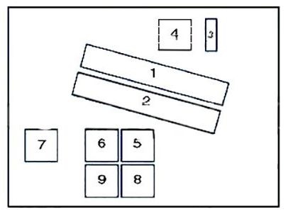
Fuse box in the engine compartment
Fuse Box Diagram (Engine Compartment Type 1)
| Number | Description |
|---|---|
| 1 | Engine control module |
| 2 | Transmission control module |
| 3 | Engine control module fuse |
| 4 | Engine control module relay |
| 5 | Windshield wiper motor relay I |
| 6 | Windshield wiper motor relay II |
| 7 | A / C condenser blower motor relay I |
| 8 | A / C condenser blower motor relay III |
| 9 | ABS relay |
Fuse Box Diagram (Engine Compartment Type 2)

| Number | Amperes [A] | Description |
|---|---|---|
| 1 | Engine Control Module (ECM) | |
| 2 | Transmission Control Module (TCM) | |
| 3 | Engine Control Relay (EC) | |
| 4 | Ignition coil relay – except 520i (22 6S 1) / 525i / 530i | |
| 5 | Windshield wiper motor relay 1 | |
| 6 | Windshield wiper motor relay 2 | |
| 7 | AC condenser blower motor relay 1 (up to 03/98) | |
| 8 | AC condenser blower motor relay 3 (up to 03/98) | |
| 9 | Secondary air injection (AIR) pump relay | |
| F1 | 30A | Engine Control Module (ECM);
Vapor Canister Purge (EVAP) valve; Mass air flow (MAF) sensor; Camshaft Position (CMP) Sensor; 1.Engine coolant thermostat – 535i / 540i. |
| F2 | 30A | Secondary Air Injection (AIR) pump;
Intake Manifold Air Control Solenoid; Injectors (except 520i (22 6S1) / 525i / 530i); Engine Control Module (ECM); Canister Purge Valve (EVAP); Camshaft Position (CMP) Actuator 1 and 2; Idle speed control (ISC) actuator. |
| F3 | 20A | Crankshaft Position (CKP) sensor;
Camshaft Position (CMP) Sensor; Mass air flow (MAF) sensor. |
| F4 | 30A | Heated Oxygen Sensors (H02S);
Transmission control module (TCM). |
| F5 | 30A | Ignition coil relay – except 520i (22 6S1) / 525i / 530i |
Fuse box in the glove compartment

Assignment of fuses in glove compartment (up to 03.1998)
| Number | Amperes [A] | Description |
|---|---|---|
| F1 | 30A | Windshield wiper motor relay |
| F2 | 30A | Headlight washers |
| F3 | 15A | Horn |
| F4 | 20A | Multifunctional control module |
| F5 | 20A / 30A | Sunroof |
| F6 | 30A | Electric exterior mirror on the passenger side |
| F7 | 20A / 30A | AC condenser blower motor relay 1 |
| F8 | – | – |
| F9 | 15A | AC / heater control module |
| F10 | 30A | Seat adjustment – passenger side |
| F11 | 7.5A | Multifunctional control module – variable power steering |
| F12 | 5A | Immobilizer |
| F13 | 30A | Seat adjustment – driver’s side, steering column adjustment |
| F14 | 5A | Engine Control Module (ECM) |
| F15 | 7.5A | Transmission Control Module (TCM);
Engine oil level sensor; Alternator; Electric box temperature switch (530d). |
| F 16 | 5A | Lamp control module |
| F17 | 10 A. | Fuel pump relay;
ABS control module; Multi-function switch assembly. |
| F18 | 5A | Instrument panel |
| F19 | 5A | Overvoltage protection relay 2 |
| F20 | 5A / 7.5A | Air conditioning / heater control module;
Heated rear window relay; Tire pressure monitor control module. |
| F21 | 5A | Cigarette lighter relay;
Seat adjustment relay; Steering column adjustment relay; Garage door opener; Parking assist control module; Anti-glare interior mirror. |
| F22 | 30A | AC condenser blower motor relay 2 |
| F23 | 7.5A | Digital multifunction display – rear |
| F24 | 5A | Instrument panel;
Tire pressure monitor control module; Steering wheel position sensor. |
| F25 | 7.5A | Digital multifunction display |
| F26 | – | – |
| F27 | 30A | Multifunctional control module |
| F28 | 15A | Automatic Transmission (AT) |
| F29 | 30A | Door function control module, driver’s side |
| F30 | 25A | ABS control module |
| F31 | 10 A. | Fuel pump relay;
ABS control module; Secondary Air Injection (AIR) pump relay (gasoline). |
| F32 | 25A | Multiple switch assembly |
| F33 | – | – |
| F34 | 10 A. | Multifunction steering wheel;
Airbag unit; Heated steering wheel. |
| F35 | 5A | A / C condenser blower motor, rear |
| F36 | – | – |
| F37 | 5A | Immobilizer control module |
| F38 | 5A | Multifunctional control module;
Horn relay; Rain sensor; Shift Stop (AT) switch; Data link connector (DLC). |
| F39 | 7.5A | Vanity mirror lamps;
Rechargeable flashlight. |
| F40 | 5A | Instrument panel;
Seat adjustment control module; Airbag crash sensor; Seat belt contact switch (driver’s side). |
| F41 | 5A | Lamp control module;
Clutch Pedal Position (CPP) switch; Brake pedal position (BPP) switch. |
| F42 | 5A | SRS control module |
| F43 | 5A | Over voltage protection relay 1 |
| F44 | 5A | Multifunction steering wheel / airbag unit;
Steering wheel; Digital multi-function display – front and rear. |
| F45 | 7.5A | Multiple switch assembly |
Fuse assignment in glove compartment (from 03/1998)
| Number | Amperes [A] | Description |
|---|---|---|
| F1 | 30A | Windshield wiper motor relay |
| F2 | 30A | Headlight washers |
| F3 | 15A | Horn |
| F4 | 20A | Multifunctional control module |
| F5 | 20A / 30A | Sunroof |
| F6 | 30A | Electric exterior mirror on the passenger side |
| F7 | 20A / 30A | Cigarette lighter – front (09/00) |
| F8 | – | – |
| F9 | 15A | Air conditioning / heater control module |
| F10 | 30A | Seat adjustment – passenger side |
| F11 | 7.5A | Multifunctional control module – variable power steering |
| F12 | 5A | Immobilizer |
| F13 | 30A | Seat adjustment – driver’s side, steering column adjustment |
| F14 | 5A | Engine Control Module (ECM) |
| F15 | 7.5A | Transmission Control Module (TCM);
Engine oil level sensor; Alternator; Electric box temperature switch (530d). |
| F 16 | 5A | Lamp control module |
| F17 | 10 A. | Fuel pump relay;
ABS control module; Multi-function switch assembly. |
| F18 | 5A | Instrument panel |
| F19 | 5A | Overvoltage protection relay 2 |
| F20 | 5A / 7.5A | Air conditioning / heater control module;
Heated rear window relay; Tire pressure monitor control module. |
| F21 | 5A | Cigarette lighter relay;
Seat adjustment relay; Steering column adjustment relay; Garage door opener; Parking assist control module; Anti-glare interior mirror. |
| F22 | 25A | Fuel pump relay – 530d / 520i (226S1) / 525i / 530i |
| F23 | 7.5A | Digital multifunction display – rear |
| F24 | 5A | Instrument panel;
Tire pressure monitor control module; Steering wheel position sensor. |
| F25 | 7.5A | Digital multifunction display |
| F26 | – | – |
| F27 | 30A | Multifunctional control module |
| F28 | 15A | Automatic Transmission (AT) |
| F29 | 30A | Door function control module, driver’s side |
| F30 | 25A | ABS control module |
| F31 | 10 A. | Fuel pump relay;
ABS control module; Secondary Air Injection (AIR) pump relay (gasoline). |
| F32 | 25A | Multiple switch assembly |
| F33 | – | – |
| F34 | 10 A. | Multifunction steering wheel / airbag unit;
Heated steering wheel. |
| F35 | 5A | A / C condenser blower motor, rear |
| F36 | – | – |
| F37 | 5A | Immobilizer control module |
| F38 | 5A | Multifunctional control module;
Horn relay; Rain sensor; Shift Stop (AT) switch; Data link connector (DLC). |
| F39 | 7.5A | Vanity mirror lamps;
Rechargeable flashlight. |
| F40 | 5A | Instrument panel;
Seat adjustment control module; Airbag crash sensor; Seat belt contact switch (driver’s side). |
| F41 | 5A | Lamp control module;
Clutch Pedal Position (CPP) switch; Brake pedal position (BPP) switch. |
| F42 | 5A | SRS control module |
| F43 | 5A | Overvoltage protection relay 1 |
| F44 | 5A | Multifunction steering wheel / airbag unit;
Steering wheel; Digital multi-function display – front / rear. |
| F45 | 7.5A | Multiple switch assembly |
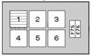
Relay block in glove box
It is located behind the fuse box.
| Number | Description |
|---|---|
| 1 | AC condenser blower motor relay 2 (up to 03/98) |
| 2 | Headlight washer pump relay |
| 3 | – |
| 4 | Starter motor relay |
| 5 | Seat adjustment relay / steering column adjustment relay |
| 6 | Heater blower relay |
| F75 | (50A) A / C condenser blower motor / Engine coolant blower motor |
| F76 | (40A) A / C / heater blower control module |
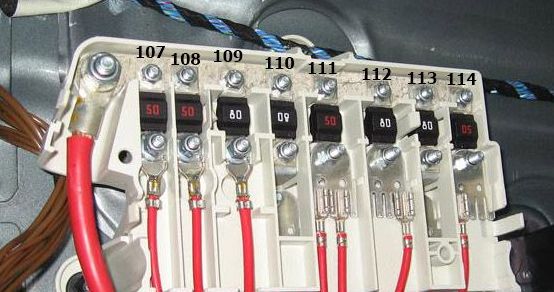
Lock in legroom
It is located on the floor under the carpeting, on the right side of the car.
| Number | Amperes [A] | Description |
|---|---|---|
| F107 | 50A | Secondary air injection (AIR) pump relay |
| F108 | 50A | ABS control module |
| F109 | 80A | Engine control (EC) relay;
Fuse Box – Engine Bay (F4 & F5). |
| F110 | 80A | Fuse box 1 (F1-F12 & F22-F25) |
| F111 | 50A | Ignition switch |
| F112 | 80A | Lamp control module |
| F113 | 80A | Seat adjustment relay / steering column adjustment relay;
Fuse Box-Console 1 (F27-F30); Fuse Box-Console 2 (F76); Lamp control module; Fuse box-console 1 (F13) -with lumbar support. |
| F114 | 50A | Ignition switch;
Data link connector (DLC). |
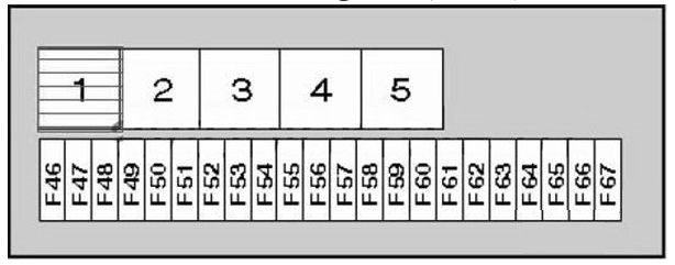
Fuse boxes in the trunk
They are located on the right side, behind the cover.
Fuse box diagram (box 1)
| Number | Amperes [A] | Description |
|---|---|---|
| 1 | Overvoltage protection relay 1 | |
| 2 | Fuel pump relay | |
| 3 | Heated rear window relay | |
| 4 | Overvoltage protection relay 2 | |
| 5 | Fuel filler flap relay | |
| F46 | – | – |
| F47 | 15A / 20A | Auxiliary heater |
| F48 | 5A | Glare-free interior mirror;
Alarm system in the car’s motion control module; Alarm system inclination sensor; Alarm system horn. |
| F49 | 30A | Suspension compressor relay |
| F50 | 7.5A | Suspension control module (with air suspension) |
| F51 | 30A | Lighter – rear |
| F52 | 30A | Cigarette lighter relay, cigarette lighter-front |
| F53 | 5A | Antenna signal amplifier;
Boot lid / tailgate lockstitch. |
| F54 | 15A | Fuel pump relay |
| F55 | 20A | Rear washer / wiper relay |
| F56 | 30A | Audio unit;
Navigation system control module; Audio unit output amplifier; Audio unit CD changer; Car monitor. |
| F57 | 10 A. | Telephone |
| F58 | 10 A. | Overvoltage protection relay 1 |
| F59 | 20A | Trailer socket |
| F60 | 15A | Suspension control module;
Multi-switch set of switches. |
| F61 | 25A | Left rear seat heating switch;
Right rear seat heating switch. |
| F62 | – | – |
| F63 | – | – |
| F64 | – | – |
| F65 | – | – |
| F66 | 40A | Heated rear window relay |
| F67 | – | – |
Assignment of fuses and relay (box 1, type 2)
| Number | Amperes [A] | Description |
|---|---|---|
| 1 | Ignition main circuits relay | |
| 2 | Fuel pump relay | |
| 3 | Heated rear window relay | |
| 4 | Ignition auxiliary circuits relay | |
| 5 | Independent heater relay | |
| F46 | 15A | independent heater / ventilation |
| F47 | 15A | independent heater |
| F48 | 5A | Alarm system |
| F49 | 30A | Air suspension system |
| F50 | 7.5A | Air suspension system |
| F51 | – | – |
| F52 | 30A | Lighter |
| F53 | 7.5A | Central lock |
| F54 | 15A | Fuel pump |
| F55 | – | – |
| F56 | 30A | Audio system;
Navigation system; On-board monitor. |
| F57 | 10 A. | Mobile phone |
| F58 | 10 A. | Audio unit;
On-board monitor; Navigation system; Telephone. |
| F59 | – | – |
| F60 | 15A | Suspension adjustment control |
| F61 | – | – |
| F62 | – | – |
| F63 | – | – |
| F64 | – | – |
| F65 | – | – |
| F66 | 40A | Heated rear window |
| F67 | – | – |
| F6S | – | – |
| F69 | – | – |
| F70 | – | – |
| F71 | – | – |
| F72 | – | – |
| F73 | – | – |
| F74 | – | – |
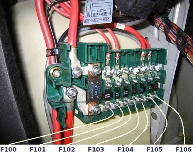
Fuse box diagram (box 2)
| Number | Amperes [A] | Description |
|---|---|---|
| F100 | 200A | Base of the fuse box (F107-F114) |
| F101 | 80A | Fuse box – load area 1 (F46-F50, F66) |
| F102 | 80A | Load area of fuse box 1 (F51-F55) |
| F103 | 50A | Trailer control module |
| F104 | 50A | Overvoltage protection relay 2 |
| F105 | 100A | Fuse box 2 (F75), auxiliary heater |
| F106 | 80A | Load area of fuse box 1 (F56-F59) |