Ford Mustang (1998-2004) – fuse and relay box
Diagrams of fuse boxes and relays – Ford Mustang
Applies to vehicles manufactured in the years:
1998, 1999, 2000, 2001, 2002, 2003, 2004.
The cigarette lighter (sockets) in the Ford Mustang is provided by fuse # 1 (cigarette lighter) in the instrument panel fuse box and fuse # 9 (auxiliary power point) in the engine compartment fuse box.
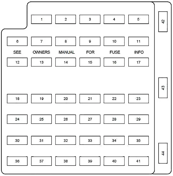
Distribution board fuse box diagram
The fuse panel is located below and to the left of the handlebar next to the brake pedal. Remove the panel cover to access the fuses.

| Number | Amperes [A] | Description |
|---|---|---|
| 1 | 20 | Lighter |
| 2 | 20 | Engine control |
| 3 | – | Not used |
| 4 | 10 | Right dipped beam headlamp |
| 5 | 15 | Instrument cluster, traction control switch |
| 6 | 20 | Starter motor relay |
| 7 | 15 | GEM, Indoor lamps |
| 8 | 20 | Engine control |
| 9 | thirty | 2002-2004: Mach 460 subwoofers |
| 10 | 10 | Left dipped beam headlamp |
| 11 | 15 | Spare lamps |
| 12 | 2 | 2003-2004: Heated PVC |
| 13 | 15 | Electronic blinker |
| 14 | – | Not used |
| 15 | 15 | Lumbar power |
| 16 | – | Not used |
| 17 | 15 | Speed control servo, shift lock actuator |
| 18 | 15 | Electronic blinker |
| 19 | 15 | Power mirror switch, GEM, anti-theft. Relay, power door locks, door ajar switches |
| 20 | 15 | Convertible top switch |
| 21 | 5 | Instrument cluster and engine control memory |
| 22 | – | Not used |
| 23 | 15 | A / C clutch, defogger switch |
| 24 | thirty | A / C blower motor |
| 25 | 25 | Release the boot lid |
| 26 | thirty | Wiper motor, wiper relays |
| 27 | 25 | Radio |
| 28 | 15 | GEM, overdrive cancel switch |
| 29 | 15 | ABS module |
| 30 | 15 | Daytime Running Lamp (DRL) Module |
| 31 | 10 | Data link connector |
| 32 | 15 | Radio, CD player (1999-2001), GEM |
| 33 | 15 | Stop lamp switch, speed control deactivation switch |
| 34 | 20 | Instrument cluster, CCRM, data link connector, Securilock transceiver |
| 35 | 15 | Shift lock actuator, PCM, speed control servo, ABS module |
| 36 | 15 | Airbag control module |
| 37 | 10 | Adjustable lighting |
| 38 | 20 | Traffic lights |
| 39 | 5 | “GEM” |
| 40 | – | Not used |
| 41 | 15 | Brake lamp |
| 42 | – | Not used |
| 43 | 20 | Circuit breaker: Power windows |
| 44 | – | Not used |
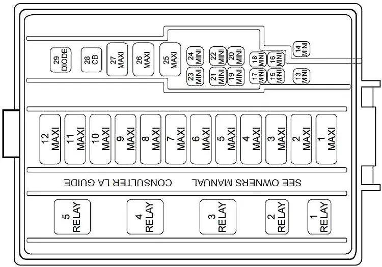
Diagram of the fuse box in the engine compartment
The power distribution box is located in the engine compartment.
| Number | Amperes [A] | Description |
|---|---|---|
| 1 | 50 | V8: Electric cooling fan motor |
| thirty | V6: Electric Cooling Fan Motor (Circuit Breaker) | |
| 2 | thirty | Headlights |
| 3 | 40 | Starter motor relay, ignition switch |
| 4 | 40 | Ignition switch |
| 5 | 40 | Ignition switch |
| 6 | 40 | I / P Fuse Panel, Instrument Cluster, Powertrain Control Module (PCM) |
| 7 | thirty | 1999-2002: Secondary Air Injection (3.8L only) |
| 8 | 50 | ABS module |
| 9 | 20 | Auxiliary power point |
| 10 | thirty | Parking lamps |
| 11 | thirty | Rear window defrosting control |
| 12 | 40 | Power Windows (1999-2002), Power Locks |
| 13 | thirty | 2003-2004: Right MACH 1000 amplifiers |
| 14 | 20 | Fuel pump |
| 15 | 10 | 1999-2002: Radio |
| thirty | 2003-2004: Left MACH 1000 amplifiers | |
| 16 | 20 | Horn |
| 17 | 20 | Wheel lock prevention system |
| 18 | 25 | Electric seats |
| 19 | 10 | 2002-2004: Intercooler pump (Cobra only) |
| 20 | 20 | Generator |
| 21 | – | Not used |
| 22 | – | Not used |
| 23 | – | Not used |
| 24 | 20 | Air conditioning pressure |
| 25 | – | Not used |
| 26 | thirty | PCM |
| 27 | 20 | DRL module, fog lamp relay |
| 28 | 25 | Switch: Convertible Top |
| R1 | Broken fog light | |
| R2 | Mat | |
| R3 | Wipers | |
| R4 | Starter | |
| R5 | Fog lights | |


