Renault Captur I (2017) – fuse and relay box
Diagrams of fuse and relay boxes – Renault Captur I
Applies to vehicles manufactured in the years:
2017.
Passenger compartment
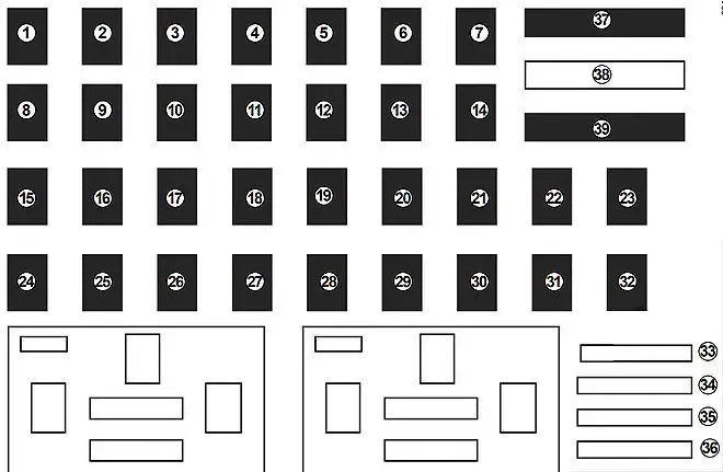
The fuse box is located behind a cover on the dashboard.

| Number | Description |
|---|---|
| 1 | Power steering;
Front seat heating; Radio. |
| 2 | Injection;
Daytime running lights. |
| 3 | Airbag |
| 4 | Automatic Transmission |
| 5 | Dipped beam |
| 6 | Front fog lights;
Side lights; Traffic lights. |
| 7 | Horn |
| 8 | Rear window wiper |
| 9 | Right-hand high beam headlamp |
| 10 | Right low beam;
Daytime running light on the right. |
| 11 | Left dipped beam |
| 12 | Left side lights;
Right and left side lights; Left daytime running light. |
| 13 | Right side lights;
Front fog lights; Rear lights on the right and left. |
| 14 | Rear window wiper |
| 15 | Central locking of opening elements |
| 16 | Electric headlight beam adjustment;
Injection. |
| 17 | Daytime running lights;
Brake lights. |
| 18 | Electric headlight beam adjustment;
Brake lights. |
| 19 | Exterior mirrors |
| 20 | ABS;
ESP. |
| 21 | Indoor lighting |
| 22 | Vehicle on / off button |
| 23 | Radio |
| 24 | Passenger compartment ECU |
| 25 | Passenger compartment ECU |
| 26 | Turn signal lamps |
| 27 | Central locking of opening elements |
| 28 | Front seat heating;
Additional heating; Radio; Daytime running lights; Brake lights; Reversing lamps; Headlight adjustment; Dimmer switch; Washer pump; Windshield wiper; Cruise control / speed limiter on / off buttons; Parking distance adjustment; Seat belt warning; Interior rearview mirror; Power steering; Starter; Fuel pump; Injection; Automatic gearbox – Control of gear shifting rules; Passenger compartment ECU; Airbag; Energy management. |
| 29 | Front row lighter;
Accessory socket; ECU in the passenger compartment; Radio. |
| 30 | Alarm |
| 31 | Instrument panel |
| 32 | Lighter |
| 33 | Rear fog lights |
| 34 | Front seat heating |
| 35 | Rear window defroster |
| 36 | Towbar |
| 37 | Windshield wiper |
| 38 | Empty location |
| 39 | Windshield wiper |
Engine compartment
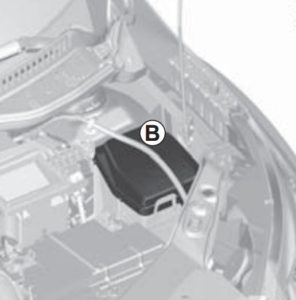
The location of the fuse box in the engine is shown in the diagram.
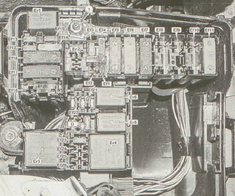
Description
| Eph1 | 7.5A ECM;
Battery current sensor. |
| Eph2 | reserve |
| Eph3 | 25A ABS / ESP stability control unit |
| Eph4 | 40A Heated rear window;
Heated exterior mirrors; The circuits of fuses F38 and F47 |
| Eph5 | 70A Fuse and relay box in passenger compartment;
Fuse circuits F5 / F23 / F24 / F25 / F26 / F27 / F42 / F44. |
| Eph6 | 80A Fuse and relay box in passenger compartment |
| Eph7 | ABS / ESP 50A stability control unit |
| Eph8 | reserve |
| Eph9 | 80A auxiliary heater * 1 |
| Eph10 | 40A Heated windshield, right side * 1 |
| Eph11 | 40A Heated windshield, left side * 1 |
| Eph12 | 30A Starter * 3 |
| Eph12 | 15A Automatic gearbox control unit * 2 |
| Eph13 | 15A Automatic gearbox control unit * 3 |
| Eph13 | Starter 30A * 2 |
| Eph14 | 25A Electronic engine management;
Fuel pump. |
| Eph15 | 15A air conditioning compressor clutch relay;
Air conditioning compressor clutch. |
| Eph 16 | 50A Electric cooling fan |
| Eph17 | 40A Automatic transmission fluid cooling fan * 3 |
| Eph18 | 80A Electric power steering pump |
| Eph19 | reserve |
| Eph20 | reserve |
| Eph21 | reserve |
| Eph22 | reserve |
| Eph23 | 15A Engine management system |
| Eph24 | reserve |
| Eph 25 | reserve |
| Eph26 | reserve |
* 1 – Depending on the configuration, * 2 – with a 1.6 engine, * 3 – with a 2.0 engine.
Relays
| Er1 | 20A Starter relay |
| Er1 | 20A Reverse light relay |
| Er2 | Alarm siren relay 20A |
| Er3 | 20 / 35A Starter relay / Coolant fan relay |
| Er4 | 35A Main engine management system relay |
| Er5 | Air conditioning compressor electromagnetic clutch relay 20A |
| Er6 | 20A fuel pump relay |


