
Renault Master III (2003-2010) – fuse and relay box
Diagrams of fuse and relay boxes – Renault Master
Applies to vehicles manufactured in the years:
2003, 2004, 2005, 2006, 2007, 2008, 2009 and 2010.
Due to the fact that Renault Master has been produced for a long time with various options for electrical equipment and body models, it is not possible to give a single general description of fuses and relays.
Passenger compartment
Fuse box
It is located under the dashboard behind the protective cover.

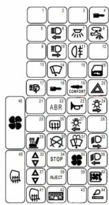
Description
- Reserve
- Reserve
- Reserve
- 20A – Anti-theft device, shock sensor
- Reserve
- 10A – Left high beam headlamp, instrument panel
- 15A – Plafond, Audio system memory, Instrument panel, Receiver for remote control of door locks, Interior lighting, Index with built-in clock, Door lock control relay, Tachograph
- 30A – Deviation of fuses of electricity consumers
- Reserve
- 10A – Right headlight (high beam)
- 7.5A – Rear fog lights, instrument panel
- Reserve
- Reserve
- 20A – Windshield wiper motor
- Reserve
- 25A – Central locking of door locks
- 30A – Headlight washer
- 2A – Connector for the diagnosis of the OBD2 on-board diagnostic system
- 5A – Air suspension
- 15A – Alarm, diagnostic connector
- Reserve
- 2A – Anti-lock brake system (ABS)
- 15A – Sound signal
- 7.5A – bulbs on the right side, illuminated license plate
- Reserve
- 5A – Rear window heating element
- 20A – Left side lamps, license plate lamps, lamps for illumination of controls and cigarette lighter switches
- Reserve
- 15A – Heated seat
- 20A – Solenoid valve for stopping diesel engines, Heating system, Injection system.
- 15A – Cleaner, windshield washer
- 10A – Right headlight (low beam)
- 25A – Electric passenger glass lift
- 20A – Stop lamps, Reversing lamps
- 20A – Electric fan for blowing air into the cabin
- 10A – Headlight washer timer, left headlight (low beam), instrument panel
- 25A – Electrically operated window in the driver’s door
- 7.5A – ECU of the injection system
- Reserve
- 20A – Audio system, tachometric relay, diesel heater relay
- 10A – Elements for heating the exterior rear-view mirrors
- 15A – Signaling device with external lighting not switched off, Instrument panel
- Reserve
- 25A – Cigarette lighter
- 40A – Electric fan for air supply to the car cabin with air conditioning
- 40A – Rear window heating element
Relay box
These modules are mounted on the passenger compartment relay board, on the left side of the dashboard.
Type 1
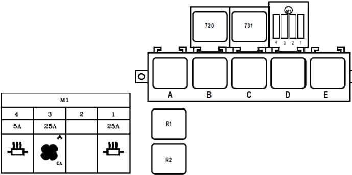
Description
| F1 | 25 | 9-seater bus:
+ Battery powered before battery cutoff heating output |
| F2 | – | 9-seater bus:
unused |
| F3 | 25 | 9-seater bus:
Condenser relay |
| F4 | 5 | 9-seater bus:
+ Battery supply before battery cut-off, heating control |
| A | + After ignition 1 | |
| B | Not in use | |
| C. | Passenger compartment fan assembly speed 4 | |
| D | Independent heating cut-off | |
| E. | Heated rear screen and side mirrors | |
| R1 | 9-seater bus:
Air conditioning + power supply after ignition |
|
| R2 | 9-seater bus:
Condenser |
|
| 720 | Air conditioning cut off | |
| 731 | Heated windscreen | |
Type 2
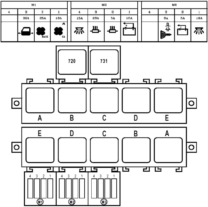
Description
| F1 | 15 | Condenser relay |
| F2 | 25 | + After ignition relay 2 |
| F3 | 30 | Electric power supply to the door after disconnecting the battery |
| F4 | – | Not in use |
| F1 | 15 | Battery cut-off relay |
| F2 | 5 | + Battery supply before battery cut-off, heating control |
| F3 | 25 | + Power supply to the battery before disconnecting the battery, heating output |
| F4 | 15 | Traffic lights and on the legs + battery power after battery cut |
| F1 | 10 | + Ignition 2 relay (299-752) power supply – electric door – passenger lighting – central locking |
| F2 | 5 | Emergency stop – circuit breaker open |
| F3 | 5 | Rear door locks + after ignition |
| F4 | – | Not in use |
| 720 | Air conditioning cut off | |
| A | + After ignition 1 | |
| B | Fog lights | |
| C. | Passenger compartment fan assembly speed 4 | |
| D | Independent heating cut-off | |
| E. | Heated rear screen and side mirrors | |
| A | Battery cut-off | |
| B | Battery disconnection lock | |
| C. | + After ignition 2 | |
| D | Evaporator | |
| E. | Condenser | |
Battery fuses
These fuses are located on the positive battery terminal.
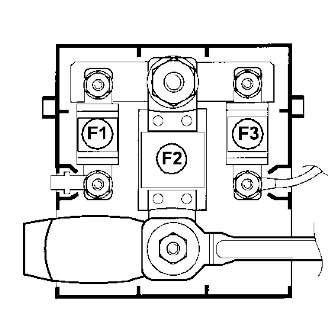
- F1 40A Fuse box in passenger compartment
- F2 – 400A – Power supply for the fuse box for the supply circuits, the starter and the starting system
- F3 – 40A – Injection computer power relay fuse