
Suzuki Kizashi (2010-2014) – fuse and relay box
Diagrams of fuse and relay boxes – Suzuki Kizashi
Applies to vehicles manufactured in the years:
2010, 2011, 2012, 2013, 2014.
Instrument panel fuse boxes
Driver’s side
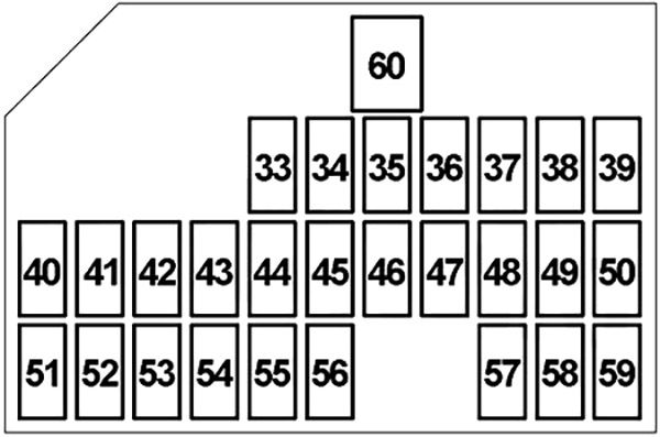
The fuses are located under the dashboard on the driver’s side. To access these fuses, pull the lower dash cover to release the latches and then remove the lower cover. The amperage of each fuse is shown at the top of the lower dash cover.
The scheme of the fuse box
| Number | Amperes [A] | Description |
|---|---|---|
| 33 | 15 | Windshield washer motor, body control module (BCM) |
| 34 | 20 | Seat heater |
| 35 | 25 | Windshield Wiper Motor, Windshield Wiper Relay, Hi / Lo Windshield Relay |
| 36 | 7.5 | Rain and light sensor, rear defogger relay, keyless start control module, sunroof module, auto dimming rear view mirror, blower motor relay, headlight washer control module |
| 37 | 15 | Generator, Ignition Coil # 1- # 4, Engine Control Module (ECM) |
| 38 | 15 | Accessory socket no.2 |
| 39 | 15 | No.1 accessory socket, power mirrors switch, keyless start control module, seat control module, audio system, navigation |
| 40 | – | – |
| 41 | – | – |
| 42 | 10 | Electronic stability program (ESP) control module, steering angle sensor |
| 43 | 7.5 | Brake light switch, cruise control |
| 44 | 7.5 | Continuously variable transmission (CVT) relay, Four-wheel drive (4WD) control module, P / S control module |
| 45 | 7.5 | – |
| 46 | 7.5 | Automatic A / C Unit, Body Control Module (BCM), Keyless Start Control Module, Combination Odometer |
| 47 | 10 | Transmission Range Sensor, Body Control Module (BCM), Parking Sensor System Control Module, ESP OFF Switch / Parking Sensor Switch, Seat Power Control Module, Auto Headlamp Leveling Control Module, HVAC Control Module, Seat Heater, Reverse Lamp Switch |
| 48 | 10 | Airbag module (SDM) |
| 49 | 15 | Keyless start control module, steering lockout |
| 50 | 7.5 | Keyless start control module, body control module (BCM) |
| 51 | 20 | Sunroof unit |
| 52 | 7.5 | Rear fog light relay |
| 53 | 10 | Tail light relay |
| 54 | 10 | Brake light switch |
| 55 | 10 | Hazard Blinker, Body Control Module (BCM) |
| 56 | 20 | Primary windshield switch, Windshield motor (driver’s side), Auxiliary windshield switch, Windshield motor (passenger’s side) |
| 57 | 15 | Audio, navigation |
| 58 | 10 | Engine Control Module (ECM), Body Control Module (BCM), Keyless Start Control Module, Engine Switch, Automatic A / C Unit, Data Link Connector (DLC), Combo Gauge, Console, Rear Dome Light, Vanity Light, Ceiling Light, Trunk Light , Glove box lighting, Foot lighting, HVAC control module |
| 59 | 20 | Door lock, body control module (BCM), fuel lid motor relay 1 and 2 |
| 60 | thirty | Window master switch, rear power window auxiliary switch |
| R1 | Ignition (IG2) | |
| R2 | Ignition (IG1) | |
| R3 | Accessory | |
| R4 | Tail light | |
Passenger’s side
The fuses are also located under the passenger side of the dashboard. Remove the two screws and remove the dashboard cover.
The scheme of the fuse box

| Number | Amperes [A] | Description |
|---|---|---|
| 61 | 20 | Rear window (right) |
| 62 | 20 | Rear window (left) |
| 63 | 20 | Main window switch, auxiliary window switch, windshield motor |
| 64 | 15 | Four-wheel drive control module (4WD) |
| 65 | 20 | Battery fan |
| 66 | – | – |
| 67 | – | – |
| 68 | – | – |
| 69 | – | – |
| 70 | – | – |
| 71 | 20 | Sound amplifier |
| 72 | thirty | Right seat (electric seat control module, lumbar support switch, electric seat auxiliary switch) |
| 73 | thirty | Left Seat (Electric Seat Control Module, Lumbar Support Switch, Electric Seat Auxiliary Switch) |
| 74 | thirty | – |
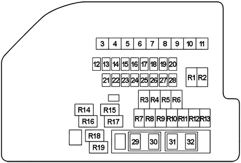
Diagram of the fuse box in the engine compartment
The main fuse, primary fuses and some single fuses are located in the engine compartment. Use the fuse puller in the fuse box to remove the fuse. The amperage of each fuse is shown on the rear of the fuse box cover.
| Number | Amperes [A] | Description |
|---|---|---|
| 3 | 50 | Blower motor relay |
| 4 | 50 | Fuse box in passenger compartment No. 2 (power window, electric seat) |
| 5 | 50 | Fuse box in passenger compartment # 1 (keyless start control module) |
| 6 | 40 | Electronic stability program (ESP) control module |
| 7 | 40 | Fuse box in passenger compartment No.1 (lights) |
| 8 | thirty | Starting motor relay |
| 9 | thirty | Radiator fan relay No.1 |
| 10 | thirty | Radiator fan relay No.3 |
| 11 | 50 | Fuse box in passenger compartment # 1 (ignition switch) |
| 12 | 25 | Fuse box in passenger compartment No. 1 (spare) |
| 13 | 25 | Electronic stability program (ESP) control module |
| 14 | 20 | Main relay (engine control) |
| 15 | 7.5 | High beam relay, dipped beam relay (left and right) |
| 16 | thirty | Headlight washer motor |
| 17 | thirty | Rear defogger relay |
| 18 | 15 | Throttle actuator control relay |
| 19 | 15 | Mirror heater relay |
| 20 | 10 | Air conditioning compressor relay |
| 21 | 15 | High beam (right) |
| 22 | 15 | High beam (left) |
| 23 | 15 | Low beam (right) or high-intensity (HID) headlamps (right) |
| 24 | 15 | Dipped beam (left) or gas discharge (HID) (left) |
| 25 | – | – |
| 26 | – | – |
| 27 | – | – |
| 28 | – | – |
| 29 | 15 | Horn |
| 30 | 15 | Heated Oxygen Sensor Relay (HO2S) |
| 31 | 20 | Front fog lamp relay |
| 32 | 15 | Continuously variable transmission (CVT) relay, transmission control module (TCM) |
| R1 | Low beam (right) | |
| R2 | Low beam (left) | |
| R3 | Air conditioning compressor | |
| R4 | Rear fog light | |
| R5 | – | |
| R6 | Traffic lights | |
| R7 | Fuel pump | |
| R8 | Engine start | |
| R9 | Windshield wiper | |
| R10 | – | |
| R11 | Hi / Lo windshield wiper | |
| R12 | – | |
| R13 | Rear defogger | |
| R14 | Throttle actuator control | |
| R15 | Radiator fan # 1 | |
| R16 | Main (motor control) | |
| R17 | Radiator fan # 3 | |
| R18 | Radiator fan # 2 | |
| R19 | Mirror heater | |
Fusible link

| Number | Amperes [A] | Description |
|---|---|---|
| 1 | 120 | All electrical circuit, battery, starting motor, generator |
| 2 | 80 | P / S control module |