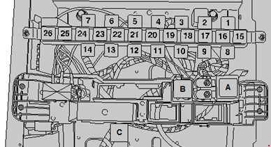
Volkswagen Crafter (2006-2022) – fuse and relay box
Diagrams of fuse and relay boxes – Volkswagen Crafter
Applies to vehicles manufactured in the years:
2006, 2007, 2008, 2009, 2010, 2011, 2012, 2013, 2014, 2015, 2016, 2017, 2018, 2019, 2020, 2021, 2022.
Box locations
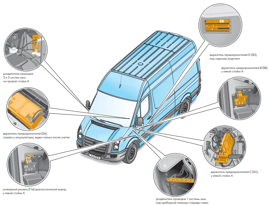
The following blocks are available on the Volkswagen Crafter:
- Mains fuse, class 30 -S190-
- Battery fuse holder A -SA-
- Fuse holder B, left post -SB-
- Left fuse and relay box C -SC-
- Fuse and relay holder D under driver seat -SD-
- Additional fuses under the driver’s seat
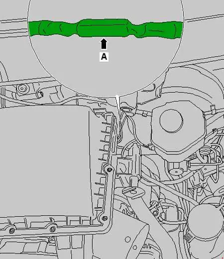
Mains fuse, class 30
Main power fuse, Grade 30, located in wiring harness between alternator and starter
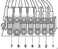
Battery fuse box
It consists of high-power fuse links.
Description
| 1 | 80A glow plug control unit |
| 2 | 40/60 / 80A Radiator fan control unit, Radiator fan |
| 3 | 80A Onboard supply control unit, engine electronics supply relay Fuse box C |
| 4 | 150A Second battery, main body fuse;
Fuse box D. |
| 5 | 150A Terminal 15 voltage supply relay, p
Sound signal relay; Onboard supply control unit Fuse box B or fuse box C |
| 6 | Relay for unloading, class 15;
Power relay 1; Heated windshield fuse; Fuse box D. |
| 7 | 150A Heating element for additional air heater |
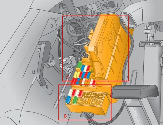
The box on the left pillar
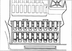
It is located on the left side of the footwell under the dashboard and consists of 2 blocks: fuse box B and fuse and relay box C.
Fuse box B
Description
| 1 | Driver door driver 25A |
| 2 | 10A diagnostic connector (T16 / 16) |
| 3 | ABS control unit 25A |
| 4 | ABS 40A control unit |
| 5 | Reserve |
| 6 | Reserve |
| 7 | 30A headlight washer pump |
| 8 | Anti-theft alarm relay 15A 1 |
| 9 | Reserve |
| 10 | 15A Control unit with display for radio and navigation system |
| 11 | 7.5 A Control unit for mobile telephone control electronics;
Tachograph control unit. |
| 12 | 30A Heating switch and heating power change;
Supply fan relay. |
| 13 | Auxiliary heater clock for 7.5 A |
| 14 | 30A Driver seat heating regulator;
Front passenger seat heating control unit. |
| 15 | 10A cargo platform illumination switch |
| 16 | 10A Heating switch and heating power change;
Air conditioning controller; CD changer. |
| 17 | Internal light switch 10A |
| 18 | Reserve |
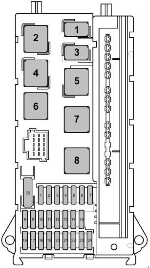
Fuse and relay box C
Description
Relays
- Horn relay
- Wiper motor switch relay 2
- Fuel pump relay
- Wiper motor changeover relay 1
- Power relay, class fifty
- Power relay terminal 15
- Relay for powering the engine electronics
- Power relay 2, grade fifteen
Description
| 1 | 15A High tone signal |
| 2 | 25A Electronic ignition lock;
El. Controller steering column lock. |
| 3 | 10A Electronic ignition lock;
Driver in the instrument panel insert; Engine controller (from May 2012). |
| 4 | 5A Light switch;
Central control panel on the front panel. |
| 5 | 30A wiper motor |
| 6 | 15A booster fuel pump |
| 7 | 5A Steering column control unit |
| 8 | 20A engine control unit; |
| 9 | 20 / 25A Fuse 6 on fuse box B (from November 2008 to May 2009);
Fuse box D (from May 2009 to November 2013). |
| 10 | 10A Air Mass Meter (from May 2012);
Reducer level estimation module (from May 2012); Crankcase ventilation heating resistor (from May 2012); Fuel pressure reducer; Reversing valve for exhaust gas recirculation cooler (from May 2012); Reducer inlet check valve (from May 2012); Pump for exhaust gas recirculation cooler (from May 2012); Reducer pump (from May 2012). |
| 11 | 15A Unloading relay 2, terminals 15 (only for vehicles of 3.8 t weight class);
Fuse 1 in fuse holder D; Fuse 2 in fuse holder D. |
| 12 | 10A Airbag control unit |
| 13 | 15A Glove box lighting switch;
Lighter. |
| 14 | 5A Light switch;
Control unit in the instrument cluster; Diagnostic connector. |
| 15 | 5A Heater switch and operation mode selection;
Headlight range adjustment; Actuator for adjusting the headlight range on the left and right side. |
| 16 | 10A Main switch of the stop-start system;
Gearbox neutral position switch; Oil level and temperature sensor; Fuel pump; Coolant pumping relay after shutdown; Motor controller; Glow plug controller; Power relay, cl. 50; Starter relay 1 (from November 2013); Starter relay 2 (from November 2013); Boost pressure regulating solenoid; Coolant circulation valve; Exhaust flap valve (from November 2013); Fuel metering valve; Exhaust gas recirculation cooler switchover valve; Lambda probe heater. |
| 17 | 10A Airbag control unit |
| 18 | 7.5A Brake light switch (from July 2006 to November 2011);
Brake pedal switch -F63- (from July 2006 to November 2011); Relay for unloading, class 15; Voltage stabilizer (from November 2011); Relay for special bodies, class 15 (from November 2011); Relay, unloading 3 for class 15 (from November 2011). |
| 19 | 7.5A Onboard supply control unit (interior lighting) |
| 20 | 25A Onboard supply control unit |
| 21 | 5A Engine control unit with air mass sensor |
| 22 | 5A Brake light switch (up to June 2006);
Brake pedal switch (up to June 2006); Lateral acceleration sensor (from July 2006); Longitudinal acceleration sensor (from July 2006); ABS controller (from July 2006). |
| 23 | 25A Starter;
Onboard supply control unit. |
| 24 | 10A Reserve, terminal -15-;
Battery regulation system controller (from May 2013). |
| 25 | 30A 12V socket |
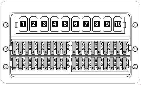
Fuse and relay box D
Under the driver’s seat
Type 1
Models released before 05.2011
Description
Relays
- Relay for special superstructures, class fifteen
- Relay for special superstructures, class 61
- Interior lighting relay, Tipping device relay (up to October 2007), Tailgate relay
- Headlight cleaning relay
- Rotary warning relay
- Anti-theft alarm relay 1
- Coolant pump relay
- Coolant circulation relay after engine shutdown
- Siren relay
- Not used
Circuit breakers
| 1 | 5A Power window control panel in the driver’s door;
Heated rear window relay (up to June 2006); Heated rear window relay 2 (from July 2006). |
| 2 | 30A Swing door rear window wiper motor |
| 3 | 5A Timer;
Gearbox neutral switch; Display control unit; Mobile phone control electronics control unit (up to May 2011); Reversing camera. |
| 4 | 7.5A Working speed adjustment switch (from July 2006);
Power take-off control sensor (from July 2006); Heated rear window relay (up to June 2006); Trailer recognition controller; Tachograph driver (from July 2006). |
| 5 | 5 / 10A Selector;
Mechanical control unit; Electronically controlled gearbox. |
| 6 | 5A Battery regulation control unit (up to May 2013);
Crankcase ventilation heating resistor. |
| 7 | 10A Fuel filter heating element |
| 8 | 5 / 10A Button of the tipping device;
Relay for special structures, class 15; 6 pin plug (from May 2007); 7-pin plug (tail lift connector). |
| 9 | 15A Roof fan switch for load space ventilation, siren relay |
| 10 | 25A For the manufacturer of superstructures and special equipment |
| 11 | 15A Relay for special bodies, class fifteen |
| 12 | 10A Relay for special superstructures, class 61 |
| 13 | 10 / 30A Evaporator fan controller (from May 2007 to May 2011);
Roof relay, turn signals (up to May 2007). |
| 14 | 20A Trailer recognition controller (up to August 2006)
9-pin connector (preparation for post-factory installation of the trailer hitch from September 2006); Hitch socket (from September 2006). |
| 15 | 25A Trailer recognition control unit |
| 16 | 7.5A Parking assist control unit;
Tire pressure sensor control unit. |
| 17 | 25A Control unit for programmable special functions |
| 18 | 25A Control unit for programmable special functions |
| 19 | 5 / 25A roof mounted electric control unit |
| 20 | 7,5 / 10A Relay for pumping coolant when turned off;
Engine entry and footwell illumination relay (from May 2009). |
| 21 | 15 / 30A Rear window defogger relay |
| 22 | 15A Rear window heater relay (up to June 2006);
Rear window heating relay 2. |
| 23 | 10 / 15A Load box lighting switch (from November 2008) 12V socket 2 |
| 24 | 15A 12V socket 4 |
| 25 | 15A 12V socket 3 |
| 26 | 25A Auxiliary heater control unit |
| 27 | 20 / 25A Additional heater control unit |
| 28 | 30 / 40A Evaporator fan controller (up to April 2007);
Transmission hydraulic pump relay (from May 2007). |
| 29 | 15A Control unit, mech. Electronically controlled gearbox |
| 30 | 40A Transmission hydraulic pump relay (up to April 2007);
Battery regulation controller. |
| 31 | 15 / 30A Rear supply fan controller;
Left sliding door control; Rear supply fan. |
| 32 | 5A Control unit for battery control |
| 33 | 15A Right sliding door control |
| 34 | 15A Heating system reducer control unit (from April 2009) |
| 35 | 3 / 15А Heating system reducer control unit (from April 2009) |
| 36 | Not used |
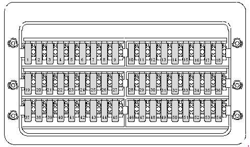
Type 2
Description
| 1 | 5A Window regulator control panel in the driver’s door;
Relay 2 for heated rear window. |
| 2 | 30A Rear window wiper motor in swing doors |
| 3 | 5A Timer;
Gearbox neutral position switch; Display panel; Reversing camera. |
| 4 | 7.5 A Switch for adjusting the working speed;
PTO monitoring sensor; Trailer detection control unit; Tachograph control unit. |
| 5 | 5 / 10A Selector;
Mech control unit; Electronically controlled gearbox; Bonnet limit switch (from November 2011). |
| 6 | 5 / 10A Heating resistor of the crankcase ventilation system;
Control unit for regulating the battery (May 2011 to May 2013). |
| 7 | 10A Fuel filter heating element |
| 8 | 5 / 10A Button of the tipping device;
Parking assist controller (from May 2013); Special superstructure relay, class 15 (up to November 2011); 6 pin connector -T6ah-; 7-pin connector -T7f- (tail lift connector). |
| 9 | 15A Switch of the roof fan for supply ventilation of the hold (until November 2011);
Siren relay (up to November 2011); Not used (from November 2011). |
| 10 | 25A For the manufacturer of superstructures and special equipment |
| 11 | 15A Relay for special bodies, class fifteen |
| 12 | 10A Relay for special superstructures, class 61 |
| 13 | Reserve |
| 14 | 20A, 9-pin connector -T9b- (preparation for installation after factory trailer hitch);
Hitch socket. |
| 15 | 25A Trailer recognition control unit |
| 16 | 7.5A Parking assist control unit;
Tire pressure sensor control unit. |
| 17 | 25A Control unit for programmable special functions |
| 18 | 25A Control unit for programmable special functions |
| 19 | 5 / 25A roof mounted electric control unit |
| 20 | 7,5 / 10A Relay for pumping coolant when turned off;
Motor relay, footwell and entrance lighting. |
| 21 | 30A Rear window defogger relay |
| 22 | 15A Rear window heater relay 2 |
| 23 | 10 / 15A Switch for load box lighting;
12 V socket 2 -U18-. |
| 24 | 15A 12V socket 4 |
| 25 | 15A 12V socket 3 |
| 26 | 25A Auxiliary heater control unit |
| 27 | 20 / 25A Additional heater control unit |
| 28 | 30 / 40A Transmission Hydraulic Pump Relay, Starter Relay 1 |
| 29 | 15A Control unit, mech. Electronically controlled gearbox |
| 30 | 5A Battery control system control unit |
| 31 | 15 / 30A Left sliding door controller (from May 2012);
Rear supply fan controller; Rear supply fan. |
| 32 | 5A Control unit for battery control |
| 33 | 7.5 / 15 / 30A Not used;
Right sliding door control unit (from May 2012); Transfer case lockout relay (from January 2012); Air compressor (from January 2012). |
| 34 | 7,5 / 15A Controller for the reducing agent heating system;
Gearbox sensor for differential lock. |
| 35 | 3 / 15A Controller for the reducing agent heating system;
Compressor protection controller (from January 2012). |
| 36 | 5A Not used (up to January 2012);
Compressor switch (from January 2012). |
| 37 | Reserve |
| 38 | Reserve |
| 39 | 7.5 / 15A Switch for the roof fan for ventilation of the cargo area (from November 2011);
Siren relay (from November 2011). |
| 40 | Reserve |
| 41 | Reserve |
| 42 | 30A Evaporator fan control unit -J349- |
| 43 | Reserve |
| 44 | Reserve |
| 45 | Reserve |
| 46 | Reserve |
| 47 | Reserve |
| 48 | Reserve |
| 49 | Reserve |
| 50 | Reserve |
| 51 | Reserve |
| 52 | Reserve |
| 53 | Reserve |
| 54 | Reserve |
| 55 | Reserve |
| 56 | Reserve |
Additional fuses
Description
| A | Battery isolation relay |
| B | Starter relay 1 |
| C. | Starter relay 2 |
| 1 | Not used |
| 2 | Relay for unloading class fifteen |
| 3 | Unloading relay 3 terminals 15;
Relay for air compressor. |
| 4 | Gearbox hydraulic pump relay;
Daytime running light switch relay. |
| 5 | Heated rear window relay |
| 6 | Heated rear window relay 2 |
| 7 | Discharge relay 2 terminals 15 |
| 8 | Not used |
| 9 | Heated windshield relay |
| 10 | Supply fan relay |
| 11 | Not used |
| 12 | Not used |
| 13 | Not used |
| 14 | Not used |
| 15 | Relay for special superstructures, class fifteen |
| 16 | Relay for special superstructures, class 61 |
| 17 | Tailgate Relay Interior Lighting Relay |
| 18 | Headlight cleaning system relay;
Air compressor unlocking relay. |
| 19 | Siren relay 2;
Entry and footwell lighting relay; Air compressor relay – regeneration. |
| 20 | Anti-theft alarm relay 1 |
| 21 | Coolant pump relay |
| 22 | Coolant circulation relay after engine shutdown |
| 23 | Siren relay;
ABS shut-off relay. |
| 24 | Relay for blocking 1 transfer case |
| 25 | Lockout Relay Distribution Box 2 |
| 26 | Relay for deactivating the reversing warning device;
Relay for locking the 3rd transfer case. |

