

Volkswagen Touareg (NF) (2010-2018) – fuse box
Volkswagen Touareg NF – fuse box diagram
Year of production: 2010, 2011, 2012, 2013, 2014, 2015, 2016, 2017, 2018.
The cigarette lighter fuse (power socket) on the Volkswagen Touareg NF is fuse 38 and 39 in the fuse box on the dashboard (right side).
The box on the left side of the dashboard
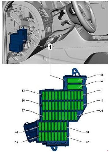
Description
| 1 | 25A Driver seat adjustment and ventilation control unit |
| 2 | Heater control unit 30A |
| 3 | 15 / 20A signal |
| 4 | 30A wiper motor |
| 5 | 30A Control for sliding sunroof |
| 6 | 15/30 Backrest release control unit |
| 7 | 15A Electrically adjustable steering column control unit |
| 8 | 5 / 10A Tire pressure monitor control unit;
Steering column control unit |
| 9 | 5A Light switch;
Rain sensor; Front roof module; Tire pressure monitoring system control unit. |
| 10 | Sunroof control unit 30A |
| 11 | 10 / 15A Steering wheel heater;
Steering column control unit. |
| 12 | Not used |
| 13 | Not used |
| 14 | 30A Onboard supply control unit |
| 15 | 25 / 30A Onboard power control unit |
| 16 | 30A Driver’s door control |
| 17 | 5 / 10A Internal sensor;
Alarm siren; Bonnet limit switch. |
| 18 | 30A Onboard supply control unit |
| 19 | 10A Engine control unit |
| 20 | 30A Onboard supply control unit;
Heater for driver and passenger seat. |
| 21 | 10A Residual heat accumulator relay |
| 22 | 30A Onboard supply control unit |
| 23 | 7.5A Diagnostic connector;
Ignition and starter switch; Data bus diagnostic interface; Electronic control unit; Steering column lock. |
| 24 | 30A Relay for heating left side of windshield |
| 25 | 30A Relay for heating the right side of the windshield |
| 26 | 15A Fan 1 battery |
| 27 | 5A Low coolant level indicator control unit;
Coolant level relay; Battery control system control unit. |
| 28 | 5A Electric actuator control unit |
| 29 | 5A Automatic transmission clutch pressure regulator |
| 30 | 5A Power steering control unit;
Electric power steering pump. |
| 31 | Not used |
| 32 | 15A Air conditioner compressor control unit |
| 33 | 30A Rear left door control unit |
| 34 | 5A Control unit for lid / tailgate opening |
| 35 | 7.5A Control unit for lid / tailgate opening |
| 36 | 5A Electromechanical parking brake button |
| 37 | 15A Fan battery 2 |
| 38 | 5A Electric drive control unit, fan relay |
| 39 | 30A Automatic transmission clutch pressure regulator |
| 40 | 30A fan unlock relay |
| 41 | 10A Control unit for the battery regulation system |
| 42 | 5A Electrochromic interior mirror |
| 43 | 7.5A Left headlight, right headlight, headlight range adjustment |
| 44 | 5A Rear seat heating control unit |
| 45 | 5A Image processing control unit;
Tilt motion sensor; Front camera for driver assistance systems. |
| 46 | 5A Lane change assistant control unit |
| 47 | 5A Parking assist controller;
Garage door opener; Data bus diagnostic interface; Diagnostic socket. |
| 48 | 10A High pressure sensor;
Air mass meter; Engine control unit; Starter relay; Engine control unit. |
| 49 | 7.5A Adaptive cruise control unit |
| 50 | 5 / 30A Igniter for driver’s side belt tensioner |
| 51 | 5A Low coolant level indicator control unit;
Coolant level relay. |
| 52 | 15A Rear window wiper motor |
| 53 | 5A Control unit for adaptive lighting and headlight range control;
Steering column control unit; On-board power control unit. |
| 54 | 15A Left headlight |
| 55 | 5A Low coolant level indicator control unit;
Coolant level relay. |
| 56 | 40A Relay compressor ride height control |
| 57 | Supply fan 40A |
The box on the right side of the dashboard
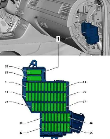
Description
| 1 | Not used |
| 2 | 15A Control unit for driving height control |
| 3 | 10A Inter-wheel differential lock control unit |
| 4 | 30A Inter-wheel differential lock control unit |
| 5 | 15 / 25A Trailer recognition control unit |
| 6 | 15A Trailer recognition control unit |
| 7 | 15 / 25A Trailer recognition control unit |
| 8 | 15 / 25A Trailer recognition control unit |
| 9 | 30A Rear right door control unit |
| 10 | Not used |
| 11 | 30A Front passenger’s door control unit |
| 12 | Not used |
| 13 | 15A Trailer recognition control unit |
| 14 | 10A Airbag control unit;Seat occupancy recognition control unit. |
| 15 | 10A Transfer case control unit |
| 16 | 5A Electromechanical parking brake controller;
Ride Height Control Panel; Washer nozzles heating resistor; ASR and ESP deactivation button; ABS controller; Downhill assist button; Electromechanical parking brake button; AUTO HOLD button; Voltage stabilizer. |
| 17 | 15A Right headlight |
| 18 | 30A Igniter for seat belt pretensioners 2, front passenger’s side |
| 19 | 5A tiptronic switch;
Multi-function switch; Automatic gearbox control unit. |
| 20 | 25A Front passenger seat adjustment controller, driver and passenger seat controls |
| 21 | 25A Rear seat heating control unit, rear air conditioning control and display panel |
| 22 | Not used |
| 23 | 25A Tailgate control unit |
| 24 | 10A Climatronic control unit, rear control panel and air conditioning display |
| 25 | 5A Outdoor camera control unit;
Reversing camera control unit. |
| 26 | 30A Rear window defogger relay |
| 27 | 5A Device for receiving the radio signal of the additional liquid heater |
| 28 | 5 / 20A Relay for gearbox hydraulic pump;
Transfer case control unit; Automatic transmission control unit (before November 2012). |
| 29 | ABS 30A control unit |
| 30 | 5A Tiptronic switch |
| 31 | 20 / 30A Central control unit for the comfort system |
| 32 | 30A Rear intake fan |
| 33 | 30A Central control unit for the comfort system |
| 34 | Not used |
| 35 | 5A Vehicle tracking system control unit |
| 36 | 30A Central control unit for the comfort system |
| 37 | 20A Automatic gearbox control unit;
Gearbox hydraulic pump relay. |
| 38 | 15A Lighter;
12V socket 2; Rear seat heating control unit (before August 2014). |
| 39 | 15A Additional 12 V sockets |
| 40 | 20 / 30A inverter with socket, 12 V – 230 V |
| 41 | 10A Connector 2 for connecting external audio devices |
| 42 | 5A Trailer recognition control unit |
| 43 | 10A Inter-wheel differential lock control unit |
| 44 | 5A air pollution sensor |
| 45 | 30A Voltage stabilizer |
| 46 | 30A Voltage stabilizer |
| 47 | 10A Electronic information system control unit |
| 48 | 30A Digital audio system control unit |
| 49 | Not used |
| 50 | 5A TV tuner;
Mobile phone electronics control unit; |
| 51 | Main unit 20A |
| 52 | 5A Control unit in instrument panel insert -J285- |
| 53 | DVD changer 5A |
| 54 | 5A Interface for external multimedia devices -R215- |
| 55 | Not used |
| 56 | ABS 40A control unit |
| 57 | 40A Electromechanical parking brake control unit;
Transfer case control unit. |
The box under the hood
It is located in the junction box in the engine compartment on the left side.
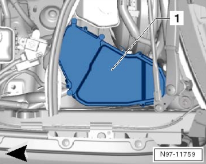
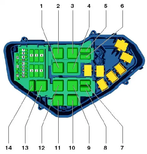
Description
| 1 | 40A Starter relay, starter |
| 2 | Not used |
| 3 | 40A Secondary air pump relay |
| 4 | 30A Vacuum pump relay |
| 5 | Not used |
| 6 | Not used |
| 7 | 15A Fuel pressure regulator, fuel metering valve, ignition coil |
| 8 | 10A Exhaust gas recirculation cooler pump |
| 9 | 30A engine control unit |
| 10 | 10A Radiator fan controller;
Glow plug controller; Additional coolant pump relay; Brake light switch; EGR cooler reversing valve; Throttle valve; Cylinder head coolant valve; Oil pressure regulating valve; Electronic engine coolant control thermostat; Throttle body. |
| 11 | 5A Oil level and temperature sensor |
| 12 | 10A Auxiliary coolant pump relay;
Residual heat accumulator relay; Coolant circulation pump. |
| 13 | 25A Fuel pump control unit |
| 14 | 15 / 30A Pump for reducing agent;
Reducing agent level estimation module; Engine controller 2. |
| 15 | 10 / 30A Terminal 30 power supply relay;
Engine control unit. |
| 16 | 30A Reducer heating system control unit |
| 17 | 15A Heater for each lambda probe |
| 18 | 10A lambda probe heating element |
Relays
- Glow plug controller (457)
- Engine electronics supply relay (645)
- Secondary air pump relay (100)
- Main relay (614)
- book
- Auxiliary coolant pump relay (404)
- book
- book
- Starter relay (100)
- Brake Servo Relay (100)
- Reserve
- book
- Starter relay 2 (433)
- book
A box under the driver’s seat
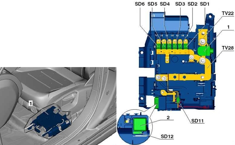
Description
| 1 | Fuse box 100A |
| 2 | 50A Control unit for driving height control |
| 3 | Fuse box 100A |
| 4 | Fuse box 80A |
| 5 | Fuse box 40A |
| 6 | 50A socket relay, fuse box |
| 7 | Fuse box 60A, rear supply fan |
| 8 | 60A wire connector, terminal 30 power relay |
| 9 | Fuse box 125A |
| 10 | 60 / 150А Heating element for additional air heater;
GB hydraulic pump relay. |
| 11 | 40A Power relay terminal 15 |
| 12 | 5A diagnostics |
Relay boxes under the dashboard
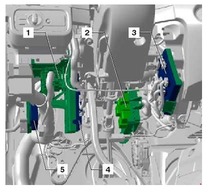
Description
- Fuse and relay box 1
- Fuse and relay box 2
- Onboard supply control unit
- Central control unit of the comfort system
- Parking assist control unit
Fuse and relay box 1
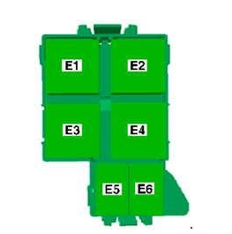
Description
| E1 | Left heated windshield relay (643) |
| E2 | Right side heated windshield relay (643);
Low coolant warning switch control unit (422). |
| E3 | Plug-in Relay (100) |
| E 4 | Gearbox Hydraulic Pump Relay (644) |
| E5 | Residual heat accumulator relay (404);
Coolant level relay (646). |
| E6 | Fan Release Relay (449) |
Fuse and relay box 2
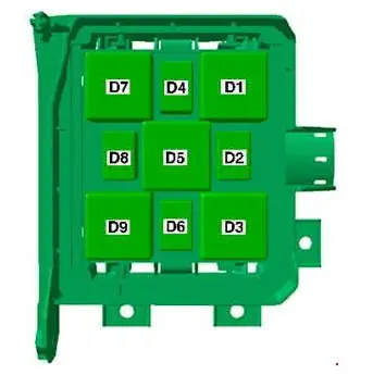
Description
| 1 | Ride height control compressor relay (373) |
| 2 | A coolant level switch (404);
Residual heat accumulator relay (646). |
| 3 | Left heated windshield relay (645) |
| 4 | Horn relay (395) |
| 5 | Gearbox hydraulic pump relay – (100);
Socket relay (644). |
| 6 | Gearbox hydraulic pump relay (404);
Gearbox hydraulic pump relay (646). |
| 7 | Heated rear window relay (643) |
| 8 | Fan release relay (646) |
| 9 | Low coolant warning switch controller (422);
Right windshield heater relay (645). |