
Volkswagen Golf VI (2008-2013) – fuse box
Volkswagen Golf VI – fuse box diagram
Year of production: 2008, 2009, 2010, 2011, 2012, 2013.
The cigarette lighter (power socket) fuse on the Volkswagen Golf VI is fuse 42 (20A) in the instrument panel fuse box.
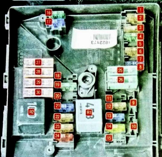
Under the hood
The fuse box is on the left side of the engine compartment.
It consists of two parts:
- main box
- high power box.
| Number | Amperes [A] / Description |
| R1 | ECU system relay;
Fan relay. |
| R2 | Air blower pump relay;
Automatic transmission control relay. |
| 1 | (30A) Wiper motor |
| 2 | (30A) Gearbox mechatronic unit |
| 3 | (20A) Onboard supply control unit |
| 4 | (20A) ABS control module |
| 5 | (15A) Transmission control module (ECM) |
| 6 | (5A) Instrument panel;
Steering column control module. |
| 7 | (40A) Cl. 15 power supply relay |
| 8 | (15A) Audio system, head unit;
(25A) Voltage stabilizer. |
| 9 | (5A) Telephone control unit |
| 10 | (5A / 10A) Electronic engine control unit;
Motronic power relay. |
| 11 | (20A) Auxiliary heater control unit;
Auxiliary heater relay. |
| 12 | (5A) CAN data bus;
Gate control unit; |
| 13 | (15A / 30A) Electronic engine control unit |
| 14 | (20A) Fuel booster pump, ignition |
| 15 | (5A / 10A) Glow plug relay;
Fuel pump relay; Lambda probe. |
| 16 | (30A) Lamps and reflectors – right side |
| 17 | (15A) Horn |
| 18 | (30A) Audio system, amplifier |
| 19 | (30A) Windshield wiper and washer |
| 20 | (10A) Coolant circulation pump;
(20A) Fuel pressure regulating valve. |
| 21 | (10A / 15A) warmed each lambda probe;
Central locking motor in the front passenger door; (20A) Brake vacuum pump. |
| 22 | (5A) Clutch pedal position switch |
| 23 | (5A / 10A / 15A) Engine management system |
| 24 | (10A) Engine management system (pump relay, injectors, etc.) |
| 25 | (40A) ABS control unit |
| 26 | (30A) Bulbs and headlights – left side;
On-board power control unit. |
| 27 | (40 / 50A) Glow plug control unit;
Secondary air pump motor. |
| 28 | (30A) Terminal 15 power relay 2 |
| 29 | (50A) Thermal fuse 1 for driver seat adjustment |
| 30 | (50A) Contact for unloading relay X |
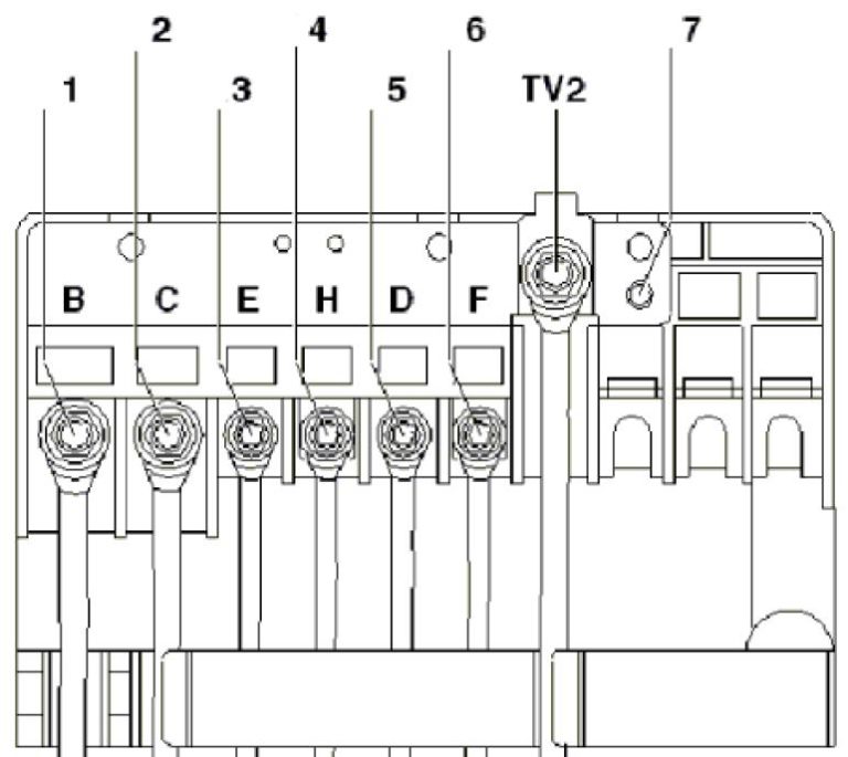
Diagram of a high-power box
Type 2
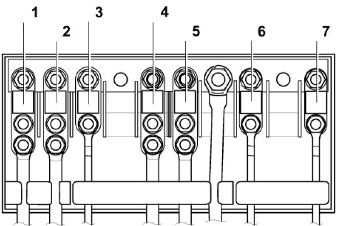
| Type 1 | |
| 1 | 150A / 200A – Generator |
| 2 | 80A – Power steering control unit |
| 3 | 50A – Radiator fan and its control unit |
| 4 | 80A – Heating relay or Accessory |
| 5 | 80A – Terminal 30, fuse box in passenger compartment |
| 6 | 40A – Low-power heating relay |
| 7 | 30/40 / 50А – Reserve |
| Type 2 | |
| 1 | 150A / 200A – Generator |
| 2 | 80A – Power steering |
| 3 | 50A – Radiator fan and its control unit |
| 4 | 80A – Reserve |
| 5 | 80A – Terminal 30, fuse box in passenger compartment |
| 6 | Reserve |
| 7 | Reserve |
In the passenger compartment
It is located at the end of the dashboard on the driver’s side, on the left-hand side.
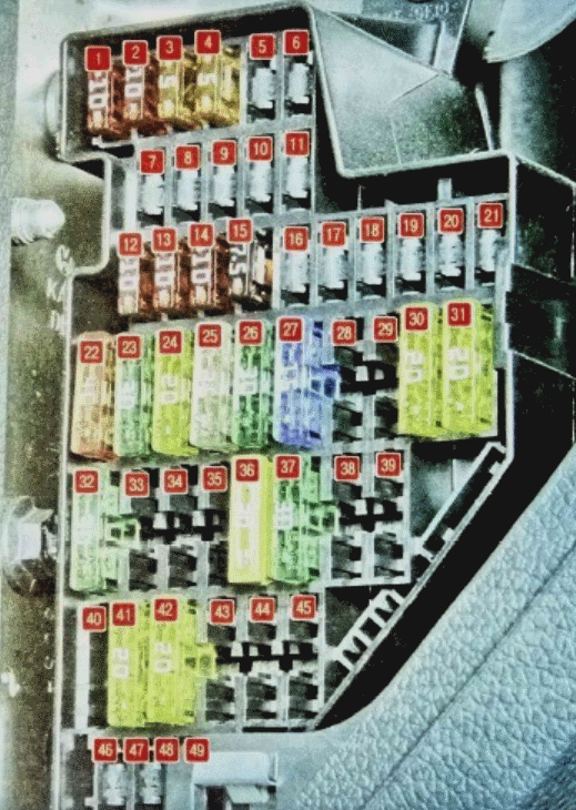
| Number | Amperes [A] / Description |
| F1 | (10A) DLC connector;
Engine control unit; Auxiliary heater operation relay; Switch and instrument cluster dimmer; Headlight range adjustment; Adaptive cruise control unit; Brake light switch. |
| F2 | (5A) ABS;
ESP; Instrument cluster control unit; Engine control unit; Starter relay; Power steering control unit; Trailer detection control unit. |
| F3 | (5A) Airbag control module |
| F4 | (5A) Oil level and temperature sensor;
High pressure sensor; Engine oil level and temperature sensor; ASR and ESP deactivation button; Tire pressure indicator button; Airbag control unit. |
| F5 | (10A) Left headlight control module |
| F6 | (10A) Right headlight control module |
| F7 | Reserve |
| F8 | Reserve |
| F9 | Reserve |
| F10 | Reserve |
| F11 | Reserve |
| F12 | (10A) Door control module (driver);
Door control module (passenger); Central lock. |
| F13 | (10A) Diagnostic socket;
Light switch; Rain and light sensor; Fog light switch. |
| F14 | (10A) Brake light switch (brake pedal position sensor);
Automatic gearbox control unit; Climatronic controller. |
| F15 | (20A) Door handle / tailgate unlock button;
On-board power control unit; Central lock. |
| F 16 | (10A) Reversing camera |
| F17 | (5 / 10A) Audio system;
Tilt sensor; Alarm siren; Signal relay. |
| F18 | Reserve |
| F19 | (5A) Failure data recorder;
Engine speed limiter control unit. |
| F20 | (20A) Entry and commissioning authorization control module;
Voltage stabilizer. |
| F21 | (10A) Electronic steering column lock control module |
| F22 | (40A) Blower |
| F23 | (30A) Electric windows;
Door control module. |
| F24 | (20A) Onboard supply control unit |
| F25 | (25A) Multi-function control module (rear window heater, air conditioner control unit, heater and operation mode selector switch) |
| F26 | (30A) Rear door control module and power windows |
| F27 | (15A) Engine management (fuel pump) |
| F28 | (15A) Voltage stabilizer, main unit |
| F29 | Reserve |
| F30 | (20A) Automatic transmission control module |
| F31 | (20A) Brake vacuum pump |
| F32 | (30A) Inverter with socket, 12 V – 230 V |
| F33 | (25A) |
| F34 | (15A) Electric seats |
| F35 | (10A) Electronic damping control module |
| F36 | (20A) Headlamp washers |
| F37 | (30A) Heated seats |
| F38 | (20A) Horn relay, anti-theft alarm;
Central control unit of the convenience system. |
| F39 | – |
| F40 | (40A) Heating / air conditioner |
| F41 | (15A) Glass cleaning motor |
| F42 | (20A) Lighter;12V socket. |
| F43 | (15A) Trailer control module |
| F44 | (20A) Trailer control module |
| F45 | (15A) Trailer control module |
| F46 | Reserve |
| F47 | (5A) Instrument cluster control module |
| F48 | (5A) Cell phone electronics control unit;
Voltage stabilizer; Magnetic field sensor for compass. |
| F49 | Reserve |
Relay boxIt is located under the dashboard itself.
Block diagram of upper relay
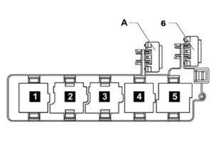
1 – Terminal + ignition relay
2 – Horn relay
3 – Headlamp washer relay
4 – Power circuit discharge relay
5 – Electric window heater relay
6 – or A – 30 A Thermal fuse 1 for adjusting the driver’s seat position