
Volkswagen Jetta VI (2011-2017) – fuse box
Volkswagen Jetta VI- fuse box diagram
Year of production: 2011, 2012, 2013, 2014, 2015, 2016, 2017.
The cigarette lighter fuse (power socket) on the Volkswagen Jetta is the F30 fuse in the fuse box in the passenger compartment.
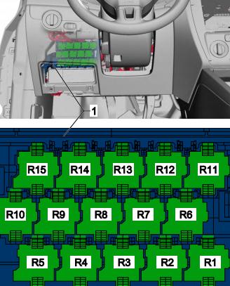
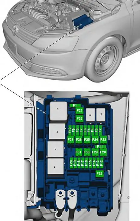
Location of the control units

Description
| 1 | ABS electronic control unit |
| 2 | Electronic air conditioner control unit |
| 3 | Battery battery |
| 4 | Diagnostic Connector (DLC) |
| 5 | Diagnostic unit |
| 6 | Driver’s door controller |
| 7 | Rear left door electrical control |
| 8 | Passenger’s door electric control unit |
| 9 | Rear right door electric control unit |
| 10 | Electronic Engine Control Module (ECM) |
| 11 | Fuse / relay box, engine compartment |
| 12 | Fuse / Relay Box, Instrument Cluster 1 |
| 13 | Fuse / relay box, instrument panel 2 |
| 14 | Glow Plug Control Box – Under Engine Fuse / Relay Box |
| 15 | Headlamp range control unit |
| 16 | Heater Blower Motor Resistor – Next to the Heater Blower Motor |
| 17 | Sound signal |
| 18 | Ignition Switch Control Module (Select Models) – In Dashboard Fuse / Relay Box 2 |
| 19 | Pilot Remote control for central locking and engine start |
| 20 | Multifunction control unit – functions: anti-theft system, central locking, charging system, door functions control units, electric load control, external lamps, foot lamps, fuel filler flap opener, fuel pump, rear view mirror heater, rear window defroster, horn, immobilizer, turn signals / hazard warning lights, instrument cluster lighting, interior lighting, remote control for central locking and engine start, rain / sun sensor, brake lights, windshield wiper / washer |
| 21 | Parking system control unit |
| 22 | Power steering controller – on the steering rack |
| 23 | Seat heating controller – under the driver’s seat |
| 24 | Steering column electronics control unit |
| 25 | Steering column lock control unit |
| 26 | SRS electronic control unit |
| 27 | Trailer electrical equipment control unit |
| 28 | Electronic Transmission Control Module (TCM) (DSG Transmission) |
| 29 | Electronic Transmission Control Module (TCM) – with automatic |
| 30 | Voltage stabilizer block |
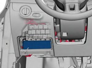
Passenger compartment
Fuse box
It is located under the steering wheel on the left side.
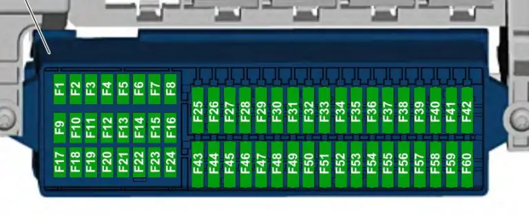
Description
Type 1
| F1 | |
| F2 | (5A) Steering column lock |
| F3 | (10A) Instrument panel |
| F4 | |
| F5 | |
| F6 | (10A) Multifunction control module |
| F7 | (5A) Fog lamp relay (AW0 only);
Switch and instrument cluster dimmer (AW0 only); Number plate lighting; On-board power control unit (AW1 only). |
| F8 | (7.5A) Windshield and headlamp washer pump switch;
Washer pump. |
| F9 | (5A) SRS system;
Airbag. |
| F10 | (10A) Right steering column switch |
| F11 | |
| F12 | |
| F13 | (5A) Electrochromic interior mirror;
Light sensor; Parking assist controller; Air pollution sensor; High pressure sensor; Climatronic air conditioning controller; Tire pressure sensor; Reverse light switch; Left washer nozzle heating resistor; Right washer nozzle heating resistor. |
| F14 | (10A) Left steering column switch;
ABS control unit; Light switch; Fuel pump control unit. |
| F15 | (10A) Dimmer for switches and instrument cluster;
Headlight range control; Auxiliary heater relay; Air mass meter; Crankcase ventilation heating resistor; Left headlight; Left headlight leveling control motor; Right headlight; Right Working Lamp range control motor. |
| F16 | (10A) Engine management |
| F17 | |
| F18 | (15A) Left headlight |
| F19 | (15A) Right headlight |
| F20 | (10A) Automatic gearbox control unit;
Gear lever sensor controller; Tiptronic switch; Air conditioning system controller; Ignition and starter switch. |
| F21 | |
| F22 | (10A) Ignition starter switch;
Converter box; Anti-theft horn; Interior sensor; Alarm siren relay; Two-tone horn relay. |
| F23 | (10A) On-board power supply control unit;
Light switch; Rain and light sensor; Magnetic field sensor for compass. |
| F24 | (10A) Onboard supply control unit;
Control unit for adaptive lighting and headlight range adjustment. |
| F25 | (15A) Gearbox |
| F26 | (15A) Brake servo vacuum pump |
| F27 | |
| F28 | (40A) Coolant heater;
Auxiliary heater relay. |
| F29 | (1A) Multifunction control module |
| F30 | (20A) Cigarette lighter sockets |
| F31 | (30A) Light switch |
| F32 | (30A) Light switch |
| F33 | (40A) Heater mode and operation mode switch;
Fresh air blower relay; Air conditioning control unit; Fresh air blower switch. |
| F34 | (15A) Left headlight;
Instrument cluster control unit. |
| F35 | (10A) Steering column control unit;Instrument cluster control unit;
Horn switch; Data bus diagnostic interface. |
| F36 | (25A) Multifunction control module |
| F37 | (15A) Left headlight |
| F38 | (15A) Right headlight |
| F39 | (15A) Dipped beam |
| F40 | (15A) Trailer control module |
| F41 | (15A) Trailer control module |
| F42 | (20A) Trailer control module |
| F43 | (30A) Passenger door control module |
| F44 | (25A) Heated rear window relay |
| F45 | (25A) Driver’s door control unit;
Front passenger’s door control unit. |
| F46 | (25A) Rear left door control unit;
Right door rear control. |
| F47 | (15A) Fuel pump |
| F48 | (20A) Multifunction control module |
| F49 | (40A) Air conditioning / heater |
| F50 | (30A) Heated seats |
| F51 | (20A) Sunroof |
| F52 | (20A) Horn |
| F53 | (15A) Heated seats |
| F54 | (15A) Rear fog lamps |
| F55 | (20A) Light switch;
Left steering column switch. |
| F56 | – |
| F57 | (15A) Audio system;Navigation system. |
| F58 | (1A / 30A) Transceiver telephone;
Inverter with socket, 12V – 230V. |
| F59 | (30A) Audio system output amplifier |
| F60 | (30A) Coolant heater |
Type 2
| F1 | (10A) Washer jet heating resistor |
| F2 | (5A / 7.5A) Steering column lock |
| F3 | (10A) Instrument panel |
| F4 | (2A / 10A) Telephone receiver / transmitter |
| F5 | (7.5A) Left rear fog lamp |
| F6 | (10A) Multifunction control module;Reversing camera. |
| F7 | (5A) Fog lamp relay;
Switch and instrument cluster dimmer; License plate lamp. |
| F8 | (7.5A) Windshield and headlamp washer pump switch;
Washer pump. |
| F9 | (5A) Airbag control module;
(15A) Seat occupancy recognition control module. |
| F10 | (10A) Right steering column switch |
| F11 | (10A) Left-hand headlight, (discharge headlamp) |
| F12 | (10A) Right-hand headlight, (gas discharge headlight) |
| F13 | (5A) Electrochromic interior mirror;
Light sensor; Parking assist controller; Air pollution sensor; High pressure sensor; Air conditioning controller; Tire pressure monitoring button; ASR and ESP switch-off button; Reverse lamp switch; Start-stop switch; Heating resistor for left washer nozzle; Right washer heating resistor; Mirror adjustment switch; Outside mirror heating button; Adaptive lighting and headlight range control. |
| F14 | (10A) Left steering column switch;
ABS controller; Fuel pump controller; Trailer Detection Controller; Voltage stabilizer; Inverter with socket, 12 V – 230 V; Data bus diagnostic interface. |
| F15 | (10A) Connector, 16 Pin (diagnostic connector);
Switch and instrument cluster dimmer; Headlight range adjustment; Fresh air blower relay; Air mass meter; Crankcase ventilation heating resistor; Vibration damping control unit; Left headlight; Left headlight range – steering actuator; Right main headlight; Right actuator controlling the headlight range. |
| F16 | (10A) Auxiliary coolant pump relay;
Fuel pump; Engine key. |
| F17 | (10A) Anti-theft system and its relay |
| F18 | (15A) Left headlight |
| F19 | (15A) Right headlight |
| F20 | (10A) Ignition and starter switch;
Tiptronic switch; Automatic gearbox control unit; Gear lever sensor controller; Climatronic controller; Radio receiver for additional water heater. |
| F21 | (15A / 20A) Onboard supply control unit;
Two-tone horn relay; High-pitched signal; Low tone signal. |
| F22 | (7.5A / 20A) Ignition and starter switch;
Converter box; Interior sensor; Alarm siren relay Anti-theft alarm horn. |
| F23 | (10A) On-board power supply control unit;
Light switch; Rain and light sensor; Magnetic field sensor for compass. |
| F24 | (10A) Control module for adaptive lighting and headlamp range control |
| F25 | (15A) Gearbox;
Automatic gearbox selector. |
| F26 | (15A) Brake servo vacuum pump |
| F27 | (1A) Airbag spiral cable with slip ring |
| F28 | (40A) Relay for auxiliary heater operation |
| F29 | (1A) Multifunction control module, ignition and starter switch |
| F30 | (20A) Cigar lighters |
| F31 | (30A) Light switch |
| F32 | (20A) Light switch |
| F33 | (40A) Heater mode and operation mode switch;
Fresh air blower relay; Air conditioning control unit; Fresh air blower switch. |
| F34 | (15A) Left high beam bulb;
Right high beam bulb; Instrument cluster control unit. |
| F35 | (10A) Steering column control module;
Data bus diagnostic interface; Horn switch. |
| F36 | (25A) Multifunction control module |
| F37 | (15A) Left-hand headlight, daytime running bulb |
| F38 | (15A) Right-hand headlight, right daytime running bulb |
| F39 | (20A) Dipped beam relay |
| F40 | (15A) Trailer control module |
| F41 | (15A) Trailer control module |
| F42 | (20A) Trailer control module |
| F43 | (30A) Passenger door control module |
| F44 | (30A) Heated rear window relay;
Heated rear window; Onboard supply control unit. |
| F45 | (30A) Driver’s door control unit;
Front passenger’s door control unit. |
| F46 | (30A) Rear left door control unit;
Right door rear control. |
| F47 | (15A) Fuel pump |
| F48 | (20A) Multifunction control module |
| F49 | (40A) Fresh air blower;
Climatronic control unit. |
| F50 | (30A) Heated seats |
| F51 | (20A) Sunroof |
| F52 | (20A) Horn |
| F53 | (15A) Driver seat lumbar adjustment switch |
| F54 | (15A) Fog lamp relay |
| F55 | (20A) Light switch;Left steering column switch. |
| F56 | (10A) Electric drive and power control electronics |
| F57 | (15A / 25A) Audio system, navigation system |
| F58 | (30A) Inverter with socket, 12V |
| F59 | (15A) Fan release relay;Battery. |
| F60 | (30A) Additional heater control unit |
Relay box
It is located above the fuse box.
Type 1
Description
- Converter, E-Box Low, (AW0)
- Supply fan relay
- Auxiliary heater operation relay
- Fuel pump (FP) relay, engine components power relay, auxiliary coolant pump relay
- Dipped beam relay
- Supply fan relay
- Terminal 75 power relay 1
- Two-tone signal relay, headlight washer relay
- Power relay (terminal 50)
- Terminal 15, power relay 2
- Heated rear window relay
- Fuel pump 2 relay, heat resistant relay, cold start injector relay, fuel priming relay
- Power relay (terminal 50)
- Terminal 15, power relay
- Fog lamp relay
Type 2
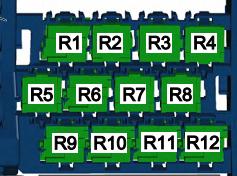
Description
- R1 – Two-tone signal relay, headlight washer relay
- R2 – power relay (terminal 50), starter relay 2
- R3 – Fuel pump relay, cold start relay
- R4 – Coolant circulation pump relay, fuel pump relay
- R5 – Terminal 75, power relay 1
- R6 – Power relay (terminal 50), starter relay
- R7 – Terminal 15, power relay
- R8 – Dipped beam relay
- R9 – Terminal 15, power relay 2
- R10 – Terminal 75, power relay 1, pitch change
- R11 – Fog lamp relay, fan relay
- R12 – Converter
Engine compartment
It is located on the right side of the battery and is covered with a protective cover.
Description
| F1 | |
| F2 | (10A / 15A) Engine management;
Engine electronics power relay. |
| F3 | (5A) Cooling fan motor;
Heating relay. |
| F4 | (5A / 10A / 15A) Engine management;
Coolant pump; Lambda probe heater. |
| F5 | (5A / 10A / 20A) Lambda probe heater;
Power supply diagnostic pump; Air mass meter; Brake vacuum pump. |
| F6 | (5A / 10A / 15A) Fuel system diagnostic pump;
Fuel tank shut-off valve; Secondary air pump relay. |
| F7 | (5A / 20A) Engine management (ignition coil);
Fuel pressure regulator. |
| F8 | (10A) Engine management (throttle body, Wastegate valve, clutch pressure regulator) |
| F9 | (5A / 15A) Glow plug driver;
Fuel pump relay. |
| F10 | (5A) Speed sensor;
Brake light switch; Brake booster relay. |
| F11 | |
| F12 | (5A / 20A) Coolant circulation pump;
The ignition coil. |
| F13 | (5A) Water pump;
(20A) Brake servo relay. |
| F14 | (5A) Engine management, main relay |
| F15 | (30A) Voltage regulator box |
| F 16 | (30A) ABS / ESP system |
| F17 | (30A) Transmission |
| F18 | (20A) Mechatronic unit for DSG gearbox |
| F19 | (1A) Multifunction control module |
| F20 | (30A) Wiper and washer relay |
| F21 | (50A) Exhaust air pump |
| F22 | (40A) Auxiliary air heater |
| F23 | (40A) ABS / ESP system |
| F24 | (50A) Trailer control module |
| F25 | (50A) Main ignition circuits, terminal 15 power relay |
| F26 | (60A) Glow plugs;(40A) Secondary air pump relay. |
| F27 | (50 / 60A) Cooling fan motor |
| F28 | (40A) Multifunction control module |
| F29 | (40A) Multifunction control module |
| F30 | (50A) Auxiliary circuits |
| F31 | (30A) Audio system output amplifier |
| F32 | (40A) Coolant heater |
Relay assignment
- Secondary air pump relay
- Coolant pump relay
- Air supply relay, Terminal 30 power relay
- –
- –
- Glow plug relay
Fuse-links department
High-power fuses in the form of fuses are located on the side.
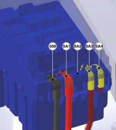
Description
- 508 – threaded connection (30) on the switch unit
- SA1 – Generator 200A
- SA2 –
- SA3 – 80A Control
- SA4 – Salon 80A, class 30, power fuses